
Installation Guide

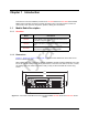
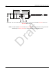
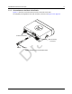
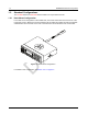
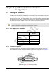
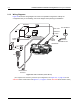
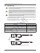
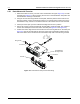
Table Of Contents
- Chapter 1 Introduction
- 1.1 Mobile Radio Description
- 1.2 Standard Configurations
- Chapter 2 Installation Details for Standard Configurations
- 2.1 Planning the Installation
- 2.2 Radio Mounting
- 2.3 Power Cable
- 2.4 Ignition Sense Cable
- 2.5 Antenna Installation
- 2.6 Microphone Hang-Up Clip
- 2.7 Completing the Installation
- Chapter 3 Options and Accessories Installation
- 3.1 Accessory Installation
- Chapter 4 Best Practices: Installation & Troubleshooting
- 4.1 Check Wiring of Ignition and Radio Ignition Sensing
- 4.2 Check Physical Installation of Radio Ground and Radio Accessory Wiring
- 4.3 Improve the Electrical Quality of the Power and Ignition Lines
- 4.4 Jump-Start the Vehicle
- 4.5 Eliminate Noise/Howling from PA Speaker
- A.1 Basic Ordering Information
- A.2 Motorola Online
- A.3 Mail Orders
- A.5 Fax Orders
- A.6 Parts Identification
- A.7 Product Customer Service
- B.1 Servicing Information
- B.2 Motorola Service Center
- B.3 Motorola Federal Technical Center
- B.4 Motorola Canadian Technical Logistics Center

Draft
2-4 Installation Details for Standard Configurations Radio Mounting
2.2.1 Dash Mount with Trunnion
1. Select the location to mount your radio on the transmission hump (see Figure 2-4) or under
the dash (see Figure 2-5). When mounting the trunnion on the transmission hump take care
the transmission housing is not affected.
2. Using the trunnion mounting bracket as a template, mark the positions of the holes on the
mounting surface. Use the innermost four holes for a curved mounting surface such as the
transmission hump, and the four outermost holes for a flat surface such as under the dash.
3. Center punch the spots you have marked and realign the trunnion in position.
4. Secure the trunnion mounting bracket with the self-drilling screws provided. The number of
screws used will depend on how the radio is mounted (see Figure 2-4 and Figure 2-5).
5. Position the radio to align the trunnion with the trunnion mounting features on the radio (see
Figure 2-4). Secure the radio with the two wing screws and lock washers (position the flat
side of the washer to the thumbscrew and the washer sharp side to the trunnion) provided.
Figure 2-4 Transmission Hump Trunnion Mounting
Wing Screw
T runnio n
Wing Screw
Threaded Hole
for Wing Screw
T ab s
Lock Washer
Lock Washer