
Installation Guide

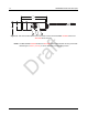
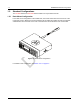
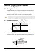
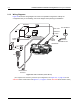
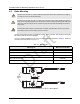
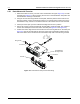
Table Of Contents
- Chapter 1 Introduction
- 1.1 Mobile Radio Description
- 1.2 Standard Configurations
- Chapter 2 Installation Details for Standard Configurations
- 2.1 Planning the Installation
- 2.2 Radio Mounting
- 2.3 Power Cable
- 2.4 Ignition Sense Cable
- 2.5 Antenna Installation
- 2.6 Microphone Hang-Up Clip
- 2.7 Completing the Installation
- Chapter 3 Options and Accessories Installation
- 3.1 Accessory Installation
- Chapter 4 Best Practices: Installation & Troubleshooting
- 4.1 Check Wiring of Ignition and Radio Ignition Sensing
- 4.2 Check Physical Installation of Radio Ground and Radio Accessory Wiring
- 4.3 Improve the Electrical Quality of the Power and Ignition Lines
- 4.4 Jump-Start the Vehicle
- 4.5 Eliminate Noise/Howling from PA Speaker
- A.1 Basic Ordering Information
- A.2 Motorola Online
- A.3 Mail Orders
- A.5 Fax Orders
- A.6 Parts Identification
- A.7 Product Customer Service
- B.1 Servicing Information
- B.2 Motorola Service Center
- B.3 Motorola Federal Technical Center
- B.4 Motorola Canadian Technical Logistics Center

Draft
2-2 Installation Details for Standard Configurations Planning the Installation
2.1.3 Wiring Diagrams
Figure 2-2 shows the wiring diagrams for some of the possible configurations. Identify the
configuration that you are installing, and use the diagram when planning the installation.
(For complete rear accessory connector pin configuration, see Figure 3-2, on page 3-2 for the
CM 2000 Series mobile radios and Figure 3-3, on page 3-3 for the XPR 2000 Series mobile radios.)
Figure 2-2 Radio Installation (Dash Mount)
BATTERY
HORN/
LIGHT
MIC
CLIP
SPEAKER
MIC
EMERGENCY
SWITCH
FUSE
FUSE
BLOCK
(+)
(-)
RED LEAD
FUSE
FIREWALL
HOLE
CONTROL HEAD
ANTENNA
CONNECTION
RF ANTENNA
IGNITION CABLE
DC
POWER
CABLE
TRUNNION