
Installation Guide

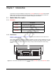
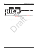
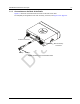
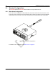
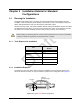
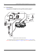
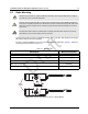
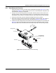
Table Of Contents
- Chapter 1 Introduction
- 1.1 Mobile Radio Description
- 1.2 Standard Configurations
- Chapter 2 Installation Details for Standard Configurations
- 2.1 Planning the Installation
- 2.2 Radio Mounting
- 2.3 Power Cable
- 2.4 Ignition Sense Cable
- 2.5 Antenna Installation
- 2.6 Microphone Hang-Up Clip
- 2.7 Completing the Installation
- Chapter 3 Options and Accessories Installation
- 3.1 Accessory Installation
- Chapter 4 Best Practices: Installation & Troubleshooting
- 4.1 Check Wiring of Ignition and Radio Ignition Sensing
- 4.2 Check Physical Installation of Radio Ground and Radio Accessory Wiring
- 4.3 Improve the Electrical Quality of the Power and Ignition Lines
- 4.4 Jump-Start the Vehicle
- 4.5 Eliminate Noise/Howling from PA Speaker
- A.1 Basic Ordering Information
- A.2 Motorola Online
- A.3 Mail Orders
- A.5 Fax Orders
- A.6 Parts Identification
- A.7 Product Customer Service
- B.1 Servicing Information
- B.2 Motorola Service Center
- B.3 Motorola Federal Technical Center
- B.4 Motorola Canadian Technical Logistics Center

Draft
Chapter 2 Installation Details for Standard
Configurations
2.1 Planning the Installation
The mobile radio operates only in negative ground electrical systems. Before starting the radio
installation, make sure that the ground polarity of the vehicle is correct. Accidentally reversing the
polarity will not damage the radio, but will cause the cable fuses to blow.
Planning is the key to fast, easy radio installation. Before starting the installation, inspect the vehicle
and determine how and where you intend to mount the antenna, radio, and accessories. Plan wire
and cable runs to provide maximum protection from pinching, crushing, and overheating.
2.1.1 Tools Required for Installation
2.1.2 Installation Example
The mobile two-way radio offers various methods of installation, with accessories placed to the
vehicle as desired. The radio can only be installed in a dash mount configuration. See Figure 2-1.
Before installing any electrical equipment, check the vehicle manufacturer’s user manual. The installation
of this device should be completed by an authorized servicer or installer.
Tool
Motorola Part
Number
Rubber-coated pliers —
Regular slot screwdriver or
Phillips #2
—
Pin removal tool 6680163F01
1/4 hex driver —
11/32 hex driver —
Figure 2-1 Typical Dash Mount Configuration
C a u t i o n
Radio
Antenna
1/4-Wavelength
Battery
Speaker