
Installation Guide

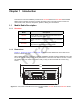
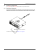
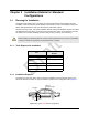
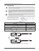
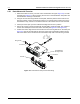
Table Of Contents
- Chapter 1 Introduction
- 1.1 Mobile Radio Description
- 1.2 Standard Configurations
- Chapter 2 Installation Details for Standard Configurations
- 2.1 Planning the Installation
- 2.2 Radio Mounting
- 2.3 Power Cable
- 2.4 Ignition Sense Cable
- 2.5 Antenna Installation
- 2.6 Microphone Hang-Up Clip
- 2.7 Completing the Installation
- Chapter 3 Options and Accessories Installation
- 3.1 Accessory Installation
- Chapter 4 Best Practices: Installation & Troubleshooting
- 4.1 Check Wiring of Ignition and Radio Ignition Sensing
- 4.2 Check Physical Installation of Radio Ground and Radio Accessory Wiring
- 4.3 Improve the Electrical Quality of the Power and Ignition Lines
- 4.4 Jump-Start the Vehicle
- 4.5 Eliminate Noise/Howling from PA Speaker
- A.1 Basic Ordering Information
- A.2 Motorola Online
- A.3 Mail Orders
- A.5 Fax Orders
- A.6 Parts Identification
- A.7 Product Customer Service
- B.1 Servicing Information
- B.2 Motorola Service Center
- B.3 Motorola Federal Technical Center
- B.4 Motorola Canadian Technical Logistics Center

Draft
1-4 Introduction Standard Configurations
1.2 Standard Configurations
The CM 2000 Series and XPR 2000 Series mobiles can only be dash mounted.
1.2.1 Dash Mount Configuration
In the dash mount configuration of the mobile radio, the control head is mounted on the front of the
transceiver housing. Electrical connection between the two takes place within the radio via a flexible
cable between the connectors on the front of the transceiver and at the back of the control head.
For details on this configuration, see Section 2.2.1 on page 2-4.
Figure 1-4 Dash Mount Configuration