
User's Manual
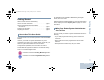
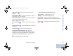
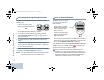
Table Of Contents
- Declaration of Conformity
- Important Safety Information
- Software Version
- Computer Software Copyrights
- Getting Started
- Identifying Radio Controls
- Identifying Status Indicators
- Receiving and Making Calls
- Advanced Features
- Radio Check
- Remote Monitor
- Scan Lists
- Scan
- Contacts Settings
- Call Indicator Settings
- Call Log Features
- Call Alert Operation
- Emergency Operation
- Text Messaging Features
- Privacy
- IP Site Connect
- Security
- Lone Worker
- Third Party Peripherals Connection Modes
- Utilities
- Setting the Squelch Level
- Setting the Power Level
- Turning the Option Board Feature(s) On or Off
- Turning the Voice Operating Transmission (VOX) Feature On or Off
- Turning the Public Address System On or Off
- Turning the External Public Address System On or Off
- Controlling the Display Backlight
- Turning Horns/Lights On or Off
- Turning the Radio Tones/Alerts On or Off
- Setting the Tone Alert Volume Offset Level
- Turning the Talk Permit Tone On or Off
- Turning the Power Up Alert Tone On or Off
- Setting the Text Message Alert Tone
- Turning the LED Indicators On or Off
- Turning the Introduction Screen On or Off
- Accessing General Radio Information
- Keypad Microphone Features
- Using the Keypad
- Additional Advanced Features
- Selecting a Zone by Alias Search
- Initiating a Radio Check by Manual Dial
- Initiating Remote Monitor by Manual Dial
- Making a Private Call by Manual Dial
- Making a Phone Call by Manual Dial
- Making a Phone Call with the One Touch Access Button
- Making a Group, Private or All Call with the Programmable Number Key
- Making a Phone Call with the Programmable Phone Button
- Making a Phone Call from Contacts
- Making a Group, Private, Phone or All Call by Alias Search
- Viewing an Entry in the Scan List by Alias Search
- Editing the Scan List by Alias Search
- Storing an Alias or ID from the Missed Call List
- Making a Call Alert by Manual Dial
- Text Messaging
- Dual Tone Multi Frequency (DTMF)
- Security
- Password Lock Features
- Accessories
- Appendix: Maritime Radio Use in the VHF Frequency Range
- Limited Warranty

Identifying Status Indicators
English
8
Identifying Status Indicators
Your radio indicates its operational status through the following:
Display Icons. . . . . . . . . . . . . . . . . . . . . . . . . . . . . . . . . page 8
Call Icons . . . . . . . . . . . . . . . . . . . . . . . . . . . . . . . . . . . page 9
Sent Item Icons . . . . . . . . . . . . . . . . . . . . . . . . . . . . . . page 10
LED Indicators. . . . . . . . . . . . . . . . . . . . . . . . . . . . . . . page 10
Audio Tones . . . . . . . . . . . . . . . . . . . . . . . . . . . . . . . . page 11
Indicator Tones . . . . . . . . . . . . . . . . . . . . . . . . . . . . . . page 12
Display Icons
The liquid crystal display (LCD) of your radio shows the radio
status, text entries, and menu entries.
The following are the icons that appear on the radio’s display.
Received Signal Strength Indicator (RSSI)
The number of bars displayed represents the radio
signal strength. Four bars indicates the strongest
signal. This icon is only displayed while receiving.
Monitor
Selected channel is being monitored.
Power Level
Radio is set at Low power.
Radio is set at High power.
Tones Disable
Tones are turned off.
Option Board
The Option Board is enabled.
Option Board Non-Function
The Option Board is disabled.
GPS Available
The GPS feature is enabled. The icon stays lit when
a position fix is available.
GPS Not Available/Out of Range
The GPS feature is enabled but is not receiving data
from the satellite.
Scan*
Scan feature is activated.
Priority Scan*
Radio detects activity on channel/group designated
as Priority 1 (if
•
is blinking) or Priority 2 (if
•
is
steady).
or
* Not applicable in Capacity Plus
NAG_6880309T15.book Page 8 Friday, January 28, 2011 10:48 AM