
Installation Manual
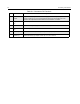
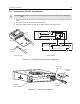
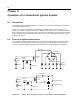
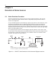
Table Of Contents
- CM200/CM300/PM400 Installation Manual
- Table of Contents
- Installation Requirements For Compliance with Radio Frequency (RF) Energy Exposure Safety Standards
- Information for Vehicles with Electronic Anti-Lock/Anti-Skid Brakes
- Chapter 1 Introduction
- Chapter 2 DC Power Cable Installation
- Chapter 3 Trunnion Installation
- Chapter 4 Antenna Installation
- Chapter 5 Installation Options
- Chapter 6 Accessory Connections
- Chapter 7 Noise Sources
- Chapter 8 Operation of a Conventional Ignition System
- Chapter 9 Detection of Noise Sources
- Chapter 10 Noise Reduction Techniques

14 Accessory Connections
11 Receiver Audio
Output
Programmable (using CPS in the Rx Audio Type): 660 mV rms (de-emphasized/
muted) or 330 mV rms (non-de-emphasized/unmuted) at 60% deviation at 1 kHz.
Default is de-emphasized/ muted. Minimum load resistance: 5 k Ohms..
12 Programmable
I/O
Input or output.
13 Switched B+ (Switched Battery Voltage) 13.8 Vdc (500 mA max.) when radio is ON.
14 Programmable
I/O
Input or output.
15 Internal Speaker Connected to internal speaker (+) and by internal jumper to pin 16.
16 External
Speaker (+)
Connect external 8 or 4 Ohm speaker to pins 1 and 16.
CAUTION: Bridge-type output. Neither pin 1 nor 16 is Ground.
Table 6-1: Connector Pin Functions
Pin Function Description