
Installation Manual
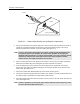
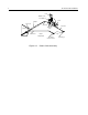
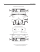
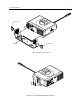
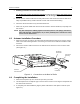
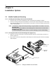
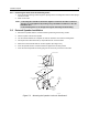
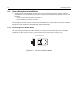
Table Of Contents
- CM200/CM300/PM400 Installation Manual
- Table of Contents
- Installation Requirements For Compliance with Radio Frequency (RF) Energy Exposure Safety Standards
- Information for Vehicles with Electronic Anti-Lock/Anti-Skid Brakes
- Chapter 1 Introduction
- Chapter 2 DC Power Cable Installation
- Chapter 3 Trunnion Installation
- Chapter 4 Antenna Installation
- Chapter 5 Installation Options
- Chapter 6 Accessory Connections
- Chapter 7 Noise Sources
- Chapter 8 Operation of a Conventional Ignition System
- Chapter 9 Detection of Noise Sources
- Chapter 10 Noise Reduction Techniques

12 Installation Options
5.3 Visor Microphone Installation
1. Carefully select the installation location for the visor-mounted microphone. Achieve optimum
performance of the microphone’s hands-free circuitry by mounting the microphone in one of two
locations:
• on the sun-visor directly above the driver, or
• on the headliner just above the driver.
The microphone should never be mounted near the window or in a place where the road and ambient
background noise would be substantially high (above 85 dB SPL).
5.3.1 Connecting to the Mobile Radio
The visor-mounted microphone cable connects to a 16-pin connector block (part of the hardware
supplied): one wire connects to pin 2, and the other wire connects to pin 7 (Figure 5.3).
Figure 5-3. 16-Pin Connector Block
12
15 16
FL0830257O
Viewed from Backside