
Installation Manual
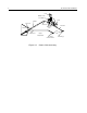
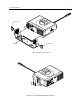
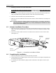
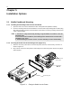
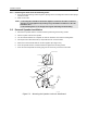
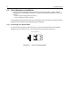
Table Of Contents
- CM200/CM300/PM400 Installation Manual
- Table of Contents
- Installation Requirements For Compliance with Radio Frequency (RF) Energy Exposure Safety Standards
- Information for Vehicles with Electronic Anti-Lock/Anti-Skid Brakes
- Chapter 1 Introduction
- Chapter 2 DC Power Cable Installation
- Chapter 3 Trunnion Installation
- Chapter 4 Antenna Installation
- Chapter 5 Installation Options
- Chapter 6 Accessory Connections
- Chapter 7 Noise Sources
- Chapter 8 Operation of a Conventional Ignition System
- Chapter 9 Detection of Noise Sources
- Chapter 10 Noise Reduction Techniques

Installation Options 11
5.1.3 Removing the Radio from the Mounting Frame
1. Push the two demounting tools through the openings in the mounting frame until the two springs
release the radio.
2. Slide out the radio.
5.2 External Speaker Installation
1. Remove the speaker from the trunnion bracket by loosening the two wing screws.
2. Choose a place to mount the speaker.
3. Use the trunnion bracket as a template to mark the locations of the three mounting holes.
4. Centerpunch and drill a 5/32-inch (4 mm) diameter hole at each location.
5. Mount the trunnion bracket with the screws supplied. (See Figure 5-2.)
6. Insert the speaker into the trunnion bracket and tighten the two wing screws.
7. Insert the external speaker accessory plug into the accessory connector of the radio.
NOTE
1. The fixing tabs should be checked for tightness each time the radio is removed.
The tabs are easily tightened by twisting a large flat-bladed screwdriver in the slot
behind the tabs.
2. The mounting frame is not designed for regular mounting and demounting.
Figure 5-2. Mounting the Speaker Under the Dashboard
Dashboard
Firewall
Trunnion Bracket
To
Firewall
Mounting
or
Dashboard
Firewall
10-16 x 5/8’’
Self-Tapping
Screw
0.157’’ (0.399cm)
Diameter
Trunnion
Bracket
Console or Floor
FL0830253O