
Installation Manual

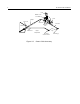


Table Of Contents
- Table of Contents
- Product Safety and RF Exposure Compliance
- Information for Vehicles with Electronic Anti-Lock/Anti-Skid Brakes
- Chapter 1 Introduction
- Chapter 2 DC Power Cable Installation
- Chapter 3 Trunnion Installation
- Chapter 4 Antenna Installation
- Chapter 5 Installation Options
- Chapter 6 Accessory Connections
- Chapter 7 Noise Sources
- Chapter 8 Operation of a Conventional Ignition System
- Chapter 9 Detection of Noise Sources
- Chapter 10 Noise Reduction Techniques

5
Chapter 3
Trunnion Installation
3.1 Planning the Mounting Trunnion Installation
Planning is the key to fast, easy radio installation. Before a hole is drilled or a wire is run, inspect the
vehicle and determine how and where you intend to mount the antenna, radio, and accessories. If you
are using any of the optional accessories, obtain them and plan for their installation using the detailed
instructions included with each accessory. Plan wire and cable runs to provide maximum protection
from pinching, crushing, and overheating.
The mounting trunnion allows the radio to be mounted to a variety of surfaces.
1. Ensure the surface can support the weight of the radio.
2. Although the mounting trunnion can be mounted to a plastic dashboard, it is recommended that
the mounting screws be located so they penetrate the supporting metal frame of the dashboard.
3.2 Trunnion Installation Procedure
1. Select either the transmission hump or an open underneath portion of the dash to mount your
radio. (See Figure 3-1.) When mounting the trunnion on the transmission hump, be careful that
the transmission housing is not affected.
2. Use the trunnion mounting bracket as a template to mark the hole positions on the mounting
surface. Use the innermost three holes for a curved mounting surface, such as the transmission
hump, and the three outermost holes for a flat surface such as under the dash.
3. Center-punch the spots you marked and use a 5/32-inch (4 mm) bit to drill a hole at each location.
4. Secure the trunnion mounting bracket to the mounting surface with the three self-tapping screws
provided. (See Figure 3-1.) Allow 3/4” clearance in front of the bracket so the locking bracket can
be inserted in the radio.
5. Attach the radio to the locking bracket using two machine screws and two external tooth
lockwashers. Tighten using a T25 Torx® driver. (Figure 3-2.)
6. Insert the locking braket and radio into the mounting bracket by first sliding the large flanges into
the slots at the rear of the mounting bracket, then slide the small locking flanges into the slots at
the front of the mounting bracket.
7. Lock the locking bracket into the mounting bracket using the key provided.
CAUTION: The locking bracket (RLN4779) is NOT recommended for overhead mounting
applications.
!