
Installation Instructions


2.2.3
Radio Locking
The section describes the radio locking on the trunnion.
2.2.3.1
Locking Kit
Enhanced Single Band Mobile Radio
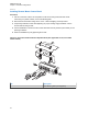
If an optional locking kit (HLN6372_) is used, position the lock housing on the trunnion after installing
the radio mounting screws. Then rotate the lock with the key in it and remove the key to lock the radio.
You can install the lock on either side of the radio, and in dash and remote mount installations.
Figure 58: Locking Kit (Optional)
1
2
3
No. Description
1 Wing Screw
2 Lock Housing
3 Lock
2.3
Power Cables (Transceiver and Control Head)
Route the RED power cable from both the radio and the control head to the vehicle battery
compartment, using accepted industry methods and standards. Be sure to grommet the firewall hole to
protect the cable.
Remove the 15 A (part number 6580283E06), 20 A (part number 6580283E07), or 30 A (part number
6580283E09) fuse from the fuseholder and connect the red lead of the radio power cable to the
positive battery terminal using the hardware provided as shown in Figure 64: HKN6188_ Power Cable
with External Speaker Connector on page 65 and Figure 65: HKN6187_ Power Cable with External
Speaker Connector, Record Audio Output Jack (2.5 mm) and Earphone Jack (2.5 mm) on page 66.
MN005720A01-AB
Chapter 2: Standard Configurations
62