
Installation Instructions


2.2.2.2
Multiple Control Head Installation
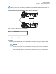
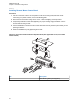
Install control heads in a multiple control head configuration as per the steps detailed in Installing
Remote Mount Control Head on page 54. Two heads can be connected to each of the two CAN
connectors on the radio, with the remaining heads connected to one or both of the first two. You can
also connect control heads in a “daisy chain” configuration from the CAN connector of a single radio.
See the following figures for examples.
NOTICE: The transceiver must be configured for Multiple Control Head through CPS
programming. Navigate to the Control Head tab in the Radio Wide section of the CPS, and
select Help for further information and tutorials.
NOTICE: In Multiple Control Head (MCH) installations, the yellow ignition sense wire must be
connected to the head assigned ID # 1. See Setting the Initial Control Head ID on page 58 for
further information.
Use the most convenient configuration for your installation, ensuring that the combined cable lengths
do not exceed 131 feet (40 meters). See Table 9: Available CAN Cables on page 57 for a list of
available CAN cable lengths. Control head ground, power and ignition sense wires (black, red, and
yellow respectively) may need more length (not supplied) in installations that locate the head more
than 10 feet from a power source.
Table 9: Available CAN Cables
Part Number Description
HKN6164_ Cable, Remote Mount, 40 m (131 ft)
HKN6165_ Cable, Remote Mount, 35 m (115 ft)
HKN6166_ Cable, Remote Mount, 23 m (75 ft)
HKN6167_ Cable, Remote Mount, 15 m (50 ft)
HKN6168_ Cable, Remote Mount, 9 m (30 ft)
HKN6169_ Cable, Remote Mount, 5 m (17 ft)
HKN6170_ Cable, Remote Mount, 3 m (10 ft)
PMLN4958_ Cable, O3 Extension, 5 m (17 ft)
Table 10: Ignition Interface Cables
Part Number Description
HLN6863_ Cable, M.A.P. 26 pin with Only Ignition and SPK
PMLN4959_ Cable, Y-Splitter with DB-25 and M.A.P. Interface
2.2.2.3
Cable Installation
Route the cables where they are protected from pinching, sharp edges or crushing. Use grommets in
any holes where the cable passes through metal panels.
Figure 41: Cabling Interconnect Diagram for Dash Mount on page 43 shows how the cables and
components are connected. It is not recommended to route cabling or wiring inside the wheel wells of a
vehicle.
MN005720A01-AB
Chapter 2: Standard Configurations
57