
Instruction Manual
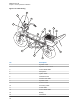


No. Description
4 Screw
5 Grommet
6 Screw
7 Lock catch
8 Radio mounting plate
9 Bottom housing
10 Ground shield plane
11 Top cover
12 Gasket
13 Hinge
14 Enclosure mounts
15 Transceiver
16 Screw
17 Trunnion
18 External tooth lock washer (8 used)
5.12
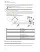
Installing the Emergency Switch Option
Use the two-conductor, green/black cable which has one end terminated with two contacts that is
supplied with the HLN5131_ Emergency Push Button.
Disconnect the emergency switch shorting plug from the accessory cable. Replace the shorting wire of
the shorting plug with the terminated end of the green/black emergency cable. Reconnect the plug to
the accessory cable.
5.13
Installing the External Alarm Relay Option
The motorcycle radio is offered with only one optional relay connection. If both horn and lights are
required, wire a second relay coil parallel to the first relay. Use the two-conductor green/black cable
which has one end terminated with two contacts that is supplied with the W116 Emergency Push
Button. Insert the contacts into positions 3 and 4 of the emergency shorting plug of the accessory
cable. Refer to Figure 119: Horn/Lights Wiring Diagram on page 123.
5.14
Installing the Headset Accessory
A six-position connector on the accessory cable has been made available for connecting a headset
accessory.
Headset manufacturers should be consulted for compatibility with the motorcycle radio prior to
purchase and installation of the headset. To install, disconnect the headset shorting plug. Remove the
headset shorting wire from the headset shorting plug. Terminate the contacts provided to the
applicable wires of the headset cable. Insert the terminated wires into the headset shorting plug per the
contact positions illustrated in the typical headset schematic found in this manual. Reconnect the
terminated headset shorting plug to the accessory cable.
MN005720A01-AB
Chapter 5: Motorcycle Radio Installation
120