
Assembly Instructions
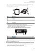


align to. Refer to band markings on radio for the proper antenna port location. For the GPS
antenna, use the 5/8-inch hole near the front of the housing near the lock.
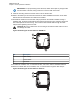
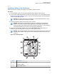
Figure 106: Location of Antenna Port
2
1
3
4
5
No. Description
1 Top Cover for Radios
2 GPS/Wi-Fi
3 Antenna
4 Enhanced Single Band Mobile Radio
5 Antenna Port
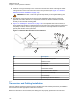
6 These holes in the metal liner is used as a template to mark the position of the holes to be drilled
at the top cover. The following guidelines provide the available options.
• Single Band – Attached your single band antenna in the appropriate antenna position.
• GPS/Wi-Fi – Mark a hole in the GPS/Wi-Fi Antenna position.
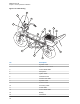
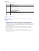
Figure 107: Enhanced Single Band Mobile Radio Antenna Band Identification
1
2
3
No. Description
1 Antenna Port
2 GPS Antenna Port
3 Wi-Fi Antenna Port
7 Remove the metal liner from the top cover.
8 For antenna positions, use the Motorola Solutions RPX-4378A Hole-Cutting Saw or equivalent,
and carefully drill a 3/4-inch hole at the marked location from the inside of the cover until the saw
bottoms out. For the GPS/Wi-Fi, carefully drill a 1 1/16-inch hole at the marked location from the
inside of the cover until the saw bottoms out. The saw should have a clean and neat circle to
ensure good contact between the antenna and the housing.
MN005720A01-AB
Chapter 5: Motorcycle Radio Installation
111