
Assembly Instructions
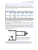


No. Description
1 Siren Cable
2 Remove the knob from the siren/PA cable connector.
3 Remove all four screws from the connector in the siren/PA cable.
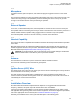
4 Open the connector cap and locate pin 8.
5 Using the contact removal tool (6684690C02), remove pin 8 from the connector.
6 Put the connector cap in place and proceed to reinstall the four screws and the knob.
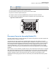
Figure 96: Location for Pin 8
1
2
3
4
5
67 8
9
A
B
2930
3132
3334
35
36
37
2324
25
26
16
17
18
19
10
11
12
13
1415
20
21
22
27
28
1
4.5
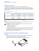
Accessory Connector Assembly Details (P2)
The APX mobile accessory connector assembly is mounted on the right rear of the radio, opposite the
antenna and next to the power connector.
It is fastened to the radio via jackscrews and held together by the two cover screws. It is a multi-
functional connector that allows for many different types of adaptations. All approved accessory wires
are securely strain-relieved through the exiting slots at the back of the accessory connector assembly.
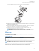
The terminations that are supplied with all accessories are fully engaged and locked into the plug
connector (6680163F01). They can also be detached for service with the assistance of a terminal
removal tool. The accessory connector assembly can be serviced multiple times for future installation
upgrades.
The accessory connector assembly, supplied with every APX mobile dash-mounted radio, is equipped
with a 26-pin plug assembly, two covers, two jackscrews, two cover screws, one emergency jumper,
one ignition sense cable assembly, and one speaker pigtail. The jumper is provided to complete the
circuit for emergency mode. If this circuit becomes open, the radio is set to emergency mode.
3980034F05 is the crimping pin part number for use with any wires used inside the accessory cable
connector.
MN005720A01-AB
Chapter 4: Options and Accessories Installation
93