
Assembly Instructions
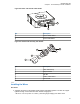
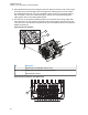
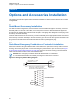
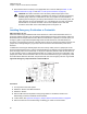


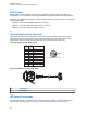

Figure 90: Gunlock Switch Redundancy Diagram
Transceiver
and
control head
VIP Cable
VIP OUT
GND
GND
GND
Gunlock
Redundancy
Wiring
Car Battery
Momentary or
time-out bypass
manual switch
4.2.5
Horn-Ring Transfer
Configure the Horn Relay for either Negative Contact or Positive Contact as shown in “section 6.3” of
the siren/PA manual (6881093C18).
Program the designated VIP-OUT line for “Horn-Ring Transfer” and program the designated VIP-IN
line for “Horn-Ring”. Figure 91: Siren/PA Horn-Ring Connections on page 89 shows wiring diagrams
for connecting the Horn-Ring through a transfer relay for both negative and positive ground systems.
Refer to the siren/PA manual (6881093C18) for more information.
MN005720A01-AB
Chapter 4: Options and Accessories Installation
88