
Assembly Instructions


Chapter 4
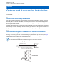
Options and Accessories Installation
This chapter provides the options and accessories installation for dash mounted and remote mounted
configurations.
4.1
Dash-Mount Accessory Installation
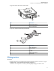
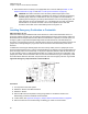
For dash-mounted configurations, the accessories must be installed through the accessory connector
assembly that is on the rear of the radio, next to the power connector. Motorola Solutions-approved
accessories are supplied with male terminals crimped to a 20-gauge wire designed to fit the plug of the
accessory connector assembly.
Insert the male terminal into the accessory connector assembly in the appropriate location and connect
the accessory connector assembly in the rear accessory port. Do not use other generic terminals in the
plug. Generic terminals cause electrical intermittences and may damage the plug.
4.1.1
Dash-Mount Emergency Pushbutton or Footswitch Installation
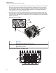
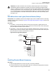
Mount the footswitch using the hardware that comes with the kit. Open the accessory cable connector
housing; remove the jumper wire. Connect the emergency switch wires to pins 14 and 15 (see Figure
87: Emergency Switch Wiring Diagram on page 84). Close the connector housing; route the finished
cable from the switch location to the control head location.
NOTICE: The emergency footswitch should be attached with A+ unattached.
A+ should be attached after successfully securing the screws in the connector.
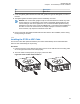
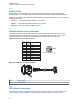
Figure 87: Emergency Switch Wiring Diagram
ACCESSORIES
CONNECTOR
J2 IN DASH MOUNT
J100 IN REMOTE MOUNT
PIN 14
PIN 15
NOTE 1
SPST NORMALLY CLOSED
EMERGENCY SWITCH
NOTE 1: REMOVE BLACK JUMPER WIRE INSIDE
ACCESSORY CONNECTOR HOUSING.
INSERT WIRES FROM EMERGENCY SWITCH
GND
EMER
1
7
8
14
13
20
21
26
MN005720A01-AB
Chapter 4: Options and Accessories Installation
84