
Installation Instructions


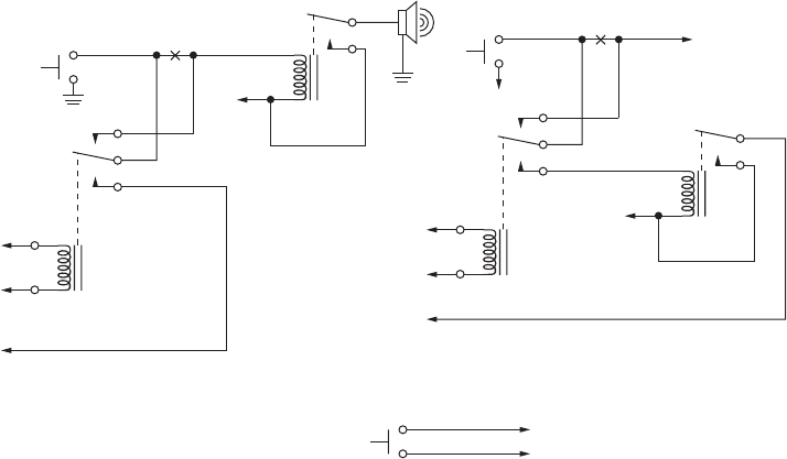
Figure 91: Siren/PA Horn-Ring Connections
To Control Head VIP
Output Programmed for
Horn-Ring Transfer
To SW B+ at
VIP Connector
Any SPDT Relay with 12V Coil
and Suitable Contact Ratings for
Vehicle Installation
Normally-Open
Momentary
Contact Pushbutton
To Control Head VIP
Output Programmed for
Horn-Ring Transfer
To SW B+ at
VIP Connector
To Control Head VIP
Input Programmed
for Horn-Ring
To DIG. GND at
VIP Connector
To Horn
Break
Here
Horn
Ring
Under Hood
Horn Relay
Break
Here
Horn
Ring
+ 12V
N.C.
N.C.
COM.
COM.
N.O.
N.O.
To VIP Input Programmed for Horn-Ring
To DIG. GND at VIP Connector
Positive-Contact Horn-Ring
Pushbutton Connections
NOTE: Locate Pushbutton
in a Location Convenient to
the Driver
+ 12V
Horn
To Control Head VIP
Input Programmed
for Horn-Ring
Negative-Contact Horn-Ring
4.2.6
Record Audio Out Jack of Transmit and Receive Audio
The use of Power Cable kit HKN6187_ (see Figure 64: HKN6187_ Power Cable with External Speaker
Connector, Record Audio Output Jack (2.5 mm) and Earphone Jack (2.5 mm) on page 64) provides
access to both the transmitted and the received audio speech. This audio can be recorded with a
standard tape recorder using a 2.5 mm connector.
4.2.7
Earphone Jack
The use of Power Cable kit HKN6187_ (see Figure 64: HKN6187_ Power Cable with External Speaker
Connector, Record Audio Output Jack (2.5 mm) and Earphone Jack (2.5 mm) on page 64) allows the
use of a standard earphone/headset instead of the external speaker. Once a cable is plugged into this
2.5 mm jack, the external speaker attached at the control head turns mute.
4.2.8
USB Data Cables
It is recommended that the USB 1.5 m data cable HKN6163_ is used for both dash mount
configurations (at J2 connector) and for remote mount configurations (at J100 connector) because the
HKN6163_ has the emergency jumper present, which is necessary for correct dash mount
configurations.
For interfacing at the MMP port, use Cable HKN6184_ which is a USB device cable. The USB 4 m (15
ft.) data cable HKN6172_ is recommended for remote mount configurations only (at J100).
If the customer intends to use the HKN6172_ for dash mount configurations (at J2), the cable
26-pin connector must be opened and an emergency jumper-wire placed across pins 14 and 15. Refer
to Figure 87: Emergency Switch Wiring Diagram on page 84.
MN005720A01-AB
Chapter 4: Options and Accessories Installation
89