
Assembly Instructions


2 Plug in the connector again.
You hear a click sound.
3 Ensure that the location of the CAN connector is correct
(such as J800L or J800R) on the transceiver interface.
4 Connect the plug from the speaker lead to the mating connector of either J2 or J626
(refer to the cabling diagram for more information).
6.1.3
Connecting the Cables for O5, E5 and O7 Control Heads
Procedure:
1 Remove the control head from its mounting trunnion.
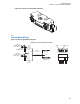
2 Plug the radio CAN cable into the proper location on the back of the control head (see Figure
47: O5 Control Head Installation Exploded View (Also applicable for O2, O7 and E5 Control
Heads) on page 53 and Figure 49: O5 Control Head Rear View (Also applicable for O2, O7 and
E5 Control Heads) on page 55).
The connectors “click” when snapped into place. The control head model can have the
microphone plugged into the lower left corner of the control head front panel.
3 Connect the plug from the speaker lead to the mating connector that comes out from the power
cable.
4 Plug the VIP connector into the correct location at the back of the control head.
5 Connect the CAN cable to the proper location on the radio.
6.1.4
Connecting the Cables for O9 Control Head
Perform the following if it has not been previously done:
Procedure:
1 Remove the control head from its mounting trunnion.
2 Plug the radio CAN cable into the proper location on the back of the control head (see Figure
48: O9 Control Head Installation Exploded View on page 54 and Figure 50: O9 Control Head
Rear View on page 55).
The connectors “click” when snapped into place. The control head model can have the
microphone plugged into the GCAI connection on the control head back panel.
3 Connect the plug from the speaker lead to the mating connector that comes out from the power
cable.
4 Plug the VIP connector into the correct location at the back of the control head.
5 Connect the CAN cable to the proper location on the radio.
6.2
Dust Cover Installation
To help protect and ensure that debris does not affect or damage your unused connectors, use the
provided dust covers.
Refer to the following figure to determine the correct cover for your connector.
MN005720A01-AB
Chapter 6: Finishing the Installation
126