
Assembly Instructions
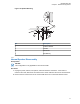


Figure 73: Disconnecting the Speaker Connector
6 Reattach the front housing assembly to the back housing assembly. Ensure that the flex is
returned to its original position and that the o-ring on the back housing assembly is not pinched.
Figure 74: Reattaching the Control Head
7 Secure the front housing assembly back to the back housing assembly with four new screws
using the Torx T-20 bit. Apply 9 in. lbs. torque for each screw.
2.6
Microphone Hang-Up Clip
This section describes the microphone hang-up clip for mobile radios.
The hang-up clip must be within reach of the operator and close enough to the control head to prevent
cable strain. Measure this distance before actually mounting the bracket. Since the bracket has a
positive-detent action, you can mount the microphone at any position.
To locate the mounting holes, use the hang-up clip as a template. To avoid interference when
removing the microphone, install the flathead screw at the top clip hole.
Some microphone models require the grounding of the microphone clip in order for HUB operation to
work correctly. Refer to the documentation that comes with your Motorola Solutions microphone model.
NOTICE: For multi-control head configuration where only one of the control heads has a
microphone, the control heads without a microphone attached must have their HUB or Monitor
pin (J100-22) jumpered by a wire to GND (J100-1 or J100-14) for HUB operation to work.
MN005720A01-AB
Chapter 2: Standard Configurations
73