
Assembly Instructions


3 Attach wires from the accessory to the appropriate wire on the VIP cable (see Table 13: VIP
Output Connections on page 91 and Table 14: VIP Input Connections on page 92).
CAUTION: The radio is sold with correct accessory cables and jumpers to have
emergency de-activated by default, regardless of the setting in Customer Programming
Software (CPS). However, if cables are not used, or if jumpers are removed without
replacing with an emergency accessory button/switch at one of the accessory ports, the
radio will power up upon the application of A+. The display may not show an indication
that the radio is on, and this can result in an incorrect operation of the radio and
excessive current drain of the vehicle battery when the engine is off.
4.2.1
Installing Emergency Pushbutton or Footswitch
When and where to use:
Mount the switch using the hardware that comes with the kit. Connect the button/switch wires to a
ground pin and the emergency pin, removing the default jumper wire in the rear accessory cable. The
button/switch shorts the pins when inactive. When the button/switch is pressed, its contact opens, the
emergency path is ungrounded and pulled-high inside the radio transceiver, and detected by the
processor. If an emergency accessory is used at either (or both) J2 connector and J626 connectors, all
jumper wires, shorting emergency to ground, must be removed so the button/switch press can be
detected.
In additional to removing the default jumper wires in accessory cables, remove a jumper part on the
printed circuit board of the TIB, in order for the button/switch to be detected. On the TIB PCB (both mid
power and high power use the same TIB), a 0 Ω jumper is placed by default so that the radio does not
go into emergency when no cable is attached at either J2 or J626 in remote mount configuration. This
jumper part, JU344, must be removed if either or both J2 and J626 have any type of emergency cable
and button/switch attached. Otherwise, the processor will never see emergency become un-grounded.
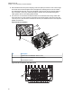
Figure 89: Emergency Jumper Removal in Remote Mount
Procedure:
1 Turn off power to the radio system.
2 Detach the TIB from the radio transceiver.
3 Detach the TIB flex.
4 Remove TIB PCB from the plastic housing using TORX T10 screwdriver. Refer to the
disassembly procedure in the Basic Service Manual.
5 Locate JU344, See Figure 89: Emergency Jumper Removal in Remote Mount on page 86.
6 Remove JU344 from the TIB PCB using a soldering gun. Clean off excess solder.
MN005720A01-AB
Chapter 4: Options and Accessories Installation
86