
Assembly Instructions

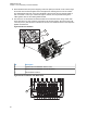


Figure 82: Power and Ground Cable Glands
1
2
No. Description
1 Ground Cable Gland
2 Power Cable Gland
Figure 83: Cable Gland Assembly with Gasket
3
2
1
5
4
No. Description
1 Cable Gland Body
2 Neoprene Seal
3 Cap Nut
4 Gasket, Cable Gland
5 Counter Nut
3.2.3
Installing the Wires
Procedure:
1 Assemble the wires into the lightbar gasket retainer and lightbar gasket. The URC can support
lightbars through control wires with outer diameter ranging from
1.52 mm to 3.77 mm (0.06 in. to 0.148 in.), with wire gauges ranging from AWG 12–20.
MN005720A01-AB
Chapter 3: Universal Relay Controller Installation
81