
Assembly Instructions


No. Description
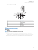
6 Adjust the universal relay controller to desired angle and secure with wing
screws
3.2
O7/O9 Universal Relay Controller Cable Assembly
This sections provides the instruction for URC cable assembly.
3.2.1
Installing the Power Cable
Procedure:
1 Remove the cap nut of power cable gland assembly, and insert the power cable through the cap
nut and neoprene seal in the cable gland body. Use power cable with either AWG 6 or AWG 8
only (recommended OD range of cable is 5.5 mm to 9 mm) that is able to withstand 80 A and 50
A respectively, to ensure water sealing of the controller. User can decide to install one or two
power cables based on the requirements. The power cables (A+) are not supplied.
2 The loose end of the power cable with cable strip length 7.94 mm (5/16”) is then placed on the
power lug and secured down by a set screw. The cap nut is then reassembled with tightening
torque 18 lb-in.
3 The other end of the power cable should be connected to circuit breaker (Motorola Solutions
part number 40012006001) end which indicates "AUX" and then, to power supply on the other
end which indicates "BAT", instead of connecting to power supply directly.
4 Repeat step 1 to step 3 to install the second power cable, if required.
5 If only one power cable is installed, it is recommended to cover the other side of the power cable
gland with power cable gland seal with tightening torque 18 lb-in.
3.2.2
Installing Ground Cable
Procedure:
1 Remove the cap nut of ground cable gland assembly, insert the ground cable through the cap
nut, and then reassemble the cap nut. Use ground cable with AWG 14 only (recommended OD
range of cable is 2 mm to 4 mm) that is able to withstand 5 A. The ground cables (A+) are not
supplied.
NOTICE: The ground is used to switch the relays, and not act as a ground to the actual
device being controlled.
2 The loose end of the ground cable with cable strip length 7.94 mm (5/16”) is then connected to a
two-pin terminal block. Both pins on the terminal block are inter-connected and either pin can be
used. The cap nut is then reassembled with tightening torque 7 lb-in.
MN005720A01-AB
Chapter 3: Universal Relay Controller Installation
80