
Wiring Diagram


MN003109A01_aa
Finishing the Installation Dust Cover Installation 6-3
6.2 Dust Cover Installation
To help protect and ensure debris does not effect or damage your unused connectors, please use
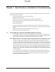
the provided dust covers. Refer to Figure 6-1 to determine which cover is for which connector.
Figure 6-1. Dust Cover Installation Locations
NOTE: Parts B and E require inserting then turning approximately 1/3 turn using a coin as a tool until
it contacts the stop.
Part C shall be installed onto DB25 accessory cable assembly when the corresponding cable
assembly connection is not in use.
Table 6-1 Dust Cover Kit Number
Kit Number Description
KT000245A01 Dash Mount
KT000246A01 Remote Mount
A: 1515047C01
B: 1515048C01
C: 7575262A01
D:SL000319A01
E: 1515327H02
Control Head
APX 8500 Rear (with no TIB)
B
C
A
E
A
Control Head (Rear)
APX 8500 Rear (with TIB)
B
A
D
D
C
D
D
C
Draft