
Wiring Diagram


MN003109A01_aa
4-4 Options and Accessories Installation Remote-Mount Accessory Installation
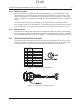
Figure 4-4. Gunlock Switch Redundancy Diagram - Mid Power
VIP OUT
GND
GND
Gunlock
Redundancy
Wiring
Car Battery
A+ into Transceiver
VIP OUT pin from
either J2 (Transceiver)
or J400 (control head)
Momentary or
time-out bypass
manual switch
Relay and Diode for
Activation of Gunlock
Draft