
Installation Manual
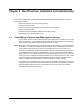
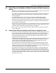
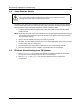


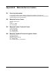


Table Of Contents
- Chapter 1 Introduction
- 1.1 Mobile Radio Description
- 1.2 Standard Configurations
- 1.3 Base/Control Stations
- Chapter 2 Installation Details for Standard Configurations
- 2.1 Planning the Installation
- 2.2 Radio Mounting
- 2.3 Power Cable
- 2.4 Ignition Sense Cable
- 2.5 Antenna Installation
- 2.6 Microphone Hang-Up Clip
- 2.7 Completing the Installation
- Chapter 3 Options and Accessories Installation
- 3.1 Accessory Installation
- Chapter 4 Best Practices: Installation & Troubleshooting
- 4.1 Check Wiring of Ignition and Radio Ignition Sensing
- 4.2 Check Physical Installation of Radio Ground and Radio Accessory Wiring
- 4.3 Improve the Electrical Quality of the Power and Ignition Lines
- 4.4 Jump-Start the Vehicle
- 4.5 Eliminate Noise/Howling from PA Speaker
- A.1 Basic Ordering Information
- A.2 Motorola Online
- A.3 Mail Orders
- A.5 Fax Orders
- A.6 Parts Identification
- A.7 Product Customer Service
- B.1 Servicing Information
- B.2 Motorola Service Center
- B.3 Motorola Federal Technical Center
- B.4 Motorola Canadian Technical Logistics Center

Index Index
A
accessories
installing
dash mount ........................................................3-1
antenna
cable, see Cables, antenna
connection ...........................................................2-13
diagrams ..............................................................2-13
installing ...............................................................2-11
mounting .............................................................. 2-11
B
base stations .............................................................1-6
black lead ..................................................................2-8
C
cables
antenna .........................................................2-4, 2-13
connection .............................................................4-1
diagrams ...............................2-2, 2-3, 2-9, 2-10, 2-13
ignition ................................................................. 2-11
ignition sense ....................................................... 2-11
power .....................................................................2-8
configurations
dash mount ............................................................1-5
control head
dash mount ............................................................1-5
see also specific model names
control stations ..........................................................1-6
D
dash mount
accessories installations ........................................3-1
configuration ..........................................................1-5
installation .......................................................2-2, 2-3
radio dimensions ....................................................1-2
trunnion ..................................................................2-5
E
emergency footswitch ................................................3-3
emergency pushbutton ..............................................3-3
F
footswitch, emergency ...............................................3-3
H
horn relay ..................................................................3-4
I
ignition
cable .................................................................... 2-11
installation
examples ...............................................................2-1
J
J2
pin configuration .............................................2-2, 2-3
L
leads
black ......................................................................2-8
light relay ...................................................................3-4
locking kit, installing ...................................................2-6
M
microphone
hang-up clip, standard .........................................2-14
S-hook ...................................................................2-5
mounting configurations ............................................2-4
dash ................................................................1-5, 2-5
O
ordering replacement parts ...................................... A-1
P
parts, ordering replacement ..................................... A-1
pin
functions ................................................................3-2
removal tool ....................................................1-1, 2-1
pin configurations
J2 ....................................................................2-2, 2-3
pushbutton, emergency .............................................3-3
R
rear accessory jack, see J2
relays
horn ........................................................................3-4
light ........................................................................3-4
replacement parts, ordering ..................................... A-1
S
speaker
connecting ...........................................................2-14
mounting ................................................................3-5
T
tools, required ............................................................2-1
trunnion