
Installation Manual
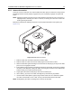


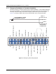

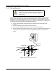

Table Of Contents
- Chapter 1 Introduction
- 1.1 Mobile Radio Description
- 1.2 Standard Configurations
- 1.3 Base/Control Stations
- Chapter 2 Installation Details for Standard Configurations
- 2.1 Planning the Installation
- 2.2 Radio Mounting
- 2.3 Power Cable
- 2.4 Ignition Sense Cable
- 2.5 Antenna Installation
- 2.6 Microphone Hang-Up Clip
- 2.7 Completing the Installation
- Chapter 3 Options and Accessories Installation
- 3.1 Accessory Installation
- Chapter 4 Best Practices: Installation & Troubleshooting
- 4.1 Check Wiring of Ignition and Radio Ignition Sensing
- 4.2 Check Physical Installation of Radio Ground and Radio Accessory Wiring
- 4.3 Improve the Electrical Quality of the Power and Ignition Lines
- 4.4 Jump-Start the Vehicle
- 4.5 Eliminate Noise/Howling from PA Speaker
- A.1 Basic Ordering Information
- A.2 Motorola Online
- A.3 Mail Orders
- A.5 Fax Orders
- A.6 Parts Identification
- A.7 Product Customer Service
- B.1 Servicing Information
- B.2 Motorola Service Center
- B.3 Motorola Federal Technical Center
- B.4 Motorola Canadian Technical Logistics Center

Options and Accessories Installation Accessory Installation 3-3
3.1.1 Emergency Pushbutton or Footswitch Installation
Mount the emergency pushbutton (Motorola part number RLN5926A_) or the footswitch (Motorola
part number RLN5929A_) using the hardware that comes with the kit. Press the terminal into the
accessory connector housing. Connect the emergency switch wires to pins 23 and 18 (see
Figure 3-3). Route the finished cable from the switch location to the control head location.
Figure 3-3 Emergency Switch Wiring Diagram
ACCESSORY
CONNECTOR
PIN 23
PIN 18
NOTE 1
SPST NORMALLY OPEN
EMERGENCY SWITCH
1
2
3
4
5
6
7
8
9
10
11
12
13
14
15
16
17
18
19
20
21
22
23
24
25
26
D+
Vbus
MAP_ID_2
SW B+
Spkr-
Tx Audio
Aux Audio Out 1 / RxD
Aux Audio Out 2 / TxD
GP5_1 (PTT)
GP5_2 (Monitor)
GP5_3 (Chan Act)
Emerg Sw
Ign Sense
D-
USB / MAP_ID Ground
MAP_ID_1
Power Ground
Spkr+
Audio Ground
Rx Audio
Ground
Ground
GP5_6
GP5_7
GP5_8
VIP_1 (Ext Alarm)