
Installation Manual


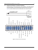


Table Of Contents
- Chapter 1 Introduction
- 1.1 Mobile Radio Description
- 1.2 Standard Configurations
- 1.3 Base/Control Stations
- Chapter 2 Installation Details for Standard Configurations
- 2.1 Planning the Installation
- 2.2 Radio Mounting
- 2.3 Power Cable
- 2.4 Ignition Sense Cable
- 2.5 Antenna Installation
- 2.6 Microphone Hang-Up Clip
- 2.7 Completing the Installation
- Chapter 3 Options and Accessories Installation
- 3.1 Accessory Installation
- Chapter 4 Best Practices: Installation & Troubleshooting
- 4.1 Check Wiring of Ignition and Radio Ignition Sensing
- 4.2 Check Physical Installation of Radio Ground and Radio Accessory Wiring
- 4.3 Improve the Electrical Quality of the Power and Ignition Lines
- 4.4 Jump-Start the Vehicle
- 4.5 Eliminate Noise/Howling from PA Speaker
- A.1 Basic Ordering Information
- A.2 Motorola Online
- A.3 Mail Orders
- A.5 Fax Orders
- A.6 Parts Identification
- A.7 Product Customer Service
- B.1 Servicing Information
- B.2 Motorola Service Center
- B.3 Motorola Federal Technical Center
- B.4 Motorola Canadian Technical Logistics Center

3-2 Options and Accessories Installation Accessory Installation
1
Pulling this line to ground will activate PTT function, activating the AUX_MIC input.
2
Fixed level (independent of volume level) received audio signal, including alert tones. Flat or de-emphasis are
programmed by CPS. Output voltage is approximately 330 mVrms per 1kHz of deviation.
3
This input is used to detect when a rear microphone accessory is taken off-hook, to override PL to alert the user to
busy traffic prior to transmitting.
4
This microphone signal is independent of the microphone signal on the front microphone connector. The nominal
input level is 80mVrms for 60% deviation. The DC impedance is 660 ohms and the AC impedance is 560 ohms.
5
See Figure 2-3 and Figure 2-12 for wiring information.
Figure 3-2 Pin Configuration of Rear Accessory Connector (as viewed from the rear of the radio)
Table 3-1 Rear Accessory Connector Pin Functions
Pin
No.
Pin Name Pin Function
Pin
No.
Pin Name Pin Function
1 USB+ USB + (Data) 14 Rx Audio Receive Live Audio
2
2 USB- USB - (Data) 15 AUX Audio 2 PUBLIC Address 2
3 VBUS
USB Power (5V from USB
accessory/cable)
16 GND Ground
4 USB/MAP_ID GND USB/MAP_ID Ground 17 GP5-1 (PTT) 5V Level GPIO, PTT Input
1
5 MAP_ID_2 Accessory Identifier 18 GND Ground
6 MAP_ID_1 Accessory Identifier 19 GP5-2 (Monitor) 5V Level GPIO, Monitor Input
3
7 SW B+ Switched Battery Voltage 20 GP5-6 5V Level GPIO
8 PWRGND Ground 21 GP5-3
5V Level GPIO, Channel
Activity Function
9 SPKR-
Speaker - (3.2 ohm minimum
impedance)
22 GP5-7 5V Level GPIO
10 SPKR+
Speaker + (3.2 ohm minimum
impedance)
23 EMERGENCY Emergency Switch Input
11 Tx Audio
Rear External Microphone
Input
4
24 GP5-8 5V Level GPIO
12 Audio GND Audio Ground 25 IGN SENSE Ignition Sense
5
13 AUX Audio 1 PUBLIC Address 1 26 VIP-1
12V Tolerant, 5V GPIO,
External Alarm
1
2
3
4
5
6
7
8
9
10
11
12
13
14
15
16
17
18
19
20
21
22
23
24
25
26
D+
Vbus
SW B+
Spkr-
Tx Audio
Aux Audio Out 1 / RxD
Aux Audio Out 2 / TxD
GP5_1 (PTT)
GP5_2 (Monitor)
GP5_3 (Chan Act)
Emerg Sw
Ign Sense
D-
USB / MAP_ID Ground
MAP_ID_1
Power Ground
Spkr+
Audio Ground
Rx Audio
Ground
Ground
GP5_6
GP5_7
GP5_8
VIP_1 (Ext Alarm)
MAP_ID_2