
Installation Manual
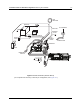
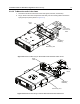
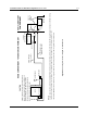
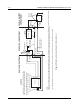
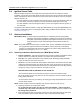
Table Of Contents
- Chapter 1 Introduction
- 1.1 Mobile Radio Description
- 1.2 Standard Configurations
- 1.3 Base/Control Stations
- Chapter 2 Installation Details for Standard Configurations
- 2.1 Planning the Installation
- 2.2 Radio Mounting
- 2.3 Power Cable
- 2.4 Ignition Sense Cable
- 2.5 Antenna Installation
- 2.6 Microphone Hang-Up Clip
- 2.7 Completing the Installation
- Chapter 3 Options and Accessories Installation
- 3.1 Accessory Installation
- Chapter 4 Best Practices: Installation & Troubleshooting
- 4.1 Check Wiring of Ignition and Radio Ignition Sensing
- 4.2 Check Physical Installation of Radio Ground and Radio Accessory Wiring
- 4.3 Improve the Electrical Quality of the Power and Ignition Lines
- 4.4 Jump-Start the Vehicle
- 4.5 Eliminate Noise/Howling from PA Speaker
- A.1 Basic Ordering Information
- A.2 Motorola Online
- A.3 Mail Orders
- A.5 Fax Orders
- A.6 Parts Identification
- A.7 Product Customer Service
- B.1 Servicing Information
- B.2 Motorola Service Center
- B.3 Motorola Federal Technical Center
- B.4 Motorola Canadian Technical Logistics Center

2-10 Installation Details for Standard Configurations Power Cable
OPERATOR COMPARTMENTRADIO COM PARTMENT
VEHICLE BATTERY
COMPARTMENT
A good chassis connection via the black primary
power cable is essential for radio operation and
to prevent damage to the radio and cable kit.
Connection to the vehicle frame is desirable.
VEHICLE
BATTERY
15A OR 20A
FUSE
PART OF
VEHICLE
WIRING
VEHICLE
IGNITION SWITCH
ON/ACC
GROMMET
GROMMET
GROMMET
RADIO POWER CABLE
(RED/BATTERY HOT)
RADIO IGNITION
CABLE (thin RED)
3A OR 4A FUSE
RADIO POWER CABLE (BLK/GROUND)
RADIO
(-)
(+)
MICROPHONE
SPEAKER
CAUTION
Rear connector
INTERFACE
CONTROL HEAD
SEE NOTE
NOTE:
Caution: if you choose to connect the radio's IGNITION line directly to the car's battery, excess use of the radio when the car's ignition is not running (i.e. alternator running)
could result in a slow discharge of the car's battery. This configuration allows the radio to operate with the car's ignition switch ON or OFF.
If the radio's IGNITION line is wired to the car's ignition switch, the radio will only function when the car's ignition switch is turned ON.
Figure 2-12 Cabling Interconnect Diagram for Remote Mount