
Installation Manual
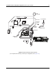
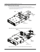
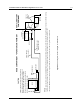
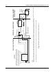
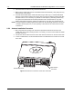
Table Of Contents
- Chapter 1 Introduction
- 1.1 Mobile Radio Description
- 1.2 Standard Configurations
- 1.3 Base/Control Stations
- Chapter 2 Installation Details for Standard Configurations
- 2.1 Planning the Installation
- 2.2 Radio Mounting
- 2.3 Power Cable
- 2.4 Ignition Sense Cable
- 2.5 Antenna Installation
- 2.6 Microphone Hang-Up Clip
- 2.7 Completing the Installation
- Chapter 3 Options and Accessories Installation
- 3.1 Accessory Installation
- Chapter 4 Best Practices: Installation & Troubleshooting
- 4.1 Check Wiring of Ignition and Radio Ignition Sensing
- 4.2 Check Physical Installation of Radio Ground and Radio Accessory Wiring
- 4.3 Improve the Electrical Quality of the Power and Ignition Lines
- 4.4 Jump-Start the Vehicle
- 4.5 Eliminate Noise/Howling from PA Speaker
- A.1 Basic Ordering Information
- A.2 Motorola Online
- A.3 Mail Orders
- A.5 Fax Orders
- A.6 Parts Identification
- A.7 Product Customer Service
- B.1 Servicing Information
- B.2 Motorola Service Center
- B.3 Motorola Federal Technical Center
- B.4 Motorola Canadian Technical Logistics Center

Installation Details for Standard Configurations Planning the Installation 2-3
Figure 2-4 Radio Installation (Remote Mount)
(For complete rear accessory connector pin configuration, see Figure 3-2.)
BA
TTE
RY
HORN/
LIGHT
MIC
CLIP
SPEAKER
MIC
EMERGENCY
SWITCH
FUSE
FUSE
BLOCK
(+)
(-)
RED LEAD
FUSE
FIREWALL
HOLE
CONTROL HEAD
ANTENNA
CONNECTION
RF ANTENNA
GPS
ANTENNA
IGNITION CABLE
DC
POWER
CABLE
TRUNNION