
User's Manual
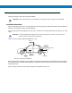
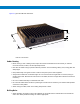
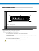
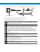

Table Of Contents
- Patents
- Warranty
- Legal Notice
- Revision History
- Introduction
- Configurations
- Chapter Descriptions
- Notational Conventions
- Related Documents
- Service Information
- Safety
- FCC Interference
- VML700 Description
- Installation
- Configuring and Monitoring the VML700
- Troubleshooting
- Using the VML700
- Specifications
- Reference

See Figure 2-8 before routing or connecting the DC Power and Ignition cable and use the following process.
Figure 2-8
DC Power and Ignition Cable Routing Into Engine Compartment
Process 2-4 describes how to install the DC power and ignition cable.
Process 2-4
How to Install the DC Power and Ignition Cable
1
Route the DC Power cable’s leads through the bulkhead and into the engine compartment. Use an existing
opening or, if necessary, drill a 2 cm (26/32 inch) diameter hole through the bulkhead. Insert a grommet into
the hole to prevent damage to the DC Power cable.
2
Cut the black lead to the desired length and connect it to the negative (-) battery terminal.
3
On the engine side of the bulkhead, connect the red (A+) lead to the vehicle’s battery as follows:
a. Cut the long red lead to the desired length. Verify that the fuse holder is at a distance of 20-30 cm away
from the connection point, ensuring that it is not close to any hot engine component.
b. Mount the fuse holder using the provided mount, and dress wires as necessary. Connect the red lead
plug adaptor (on the fuse holder) to the matching receptacle on the red lead of the DC Power cable.
c. Remove the fuse from the fuse holder and connect the red lead of the DC Power cable to the positive (+)
battery terminal. Cable tie the wire every 4” (10 cm) along its length, do not tie to existing vehicle
systems.
d. Insert the fuse into the fuse holder.
5
Verify that the cables in the engine compartment do not obstruct any of the vehicle controls or touch hot or
moveable parts of the engine.
6
For ignition installation, perform the following steps:
a. Cut the green lead to the desired length.
b. Connect the green lead of the DC Power cable to ignition (+). Cable tie the wire every 4” (10 cm) along
its length, do not tie to existing vehicle systems.
c. Verify that the voltage is high with ignition on, during cranking and while vehicle is running. When ignition
is off, the voltage is low.
7
Connect the DC Power and ignition cable connector to POWER connector on the VML700 Connectors panel.
Fasten the connector using the four fastening screws.
Power & Ignition Connector to
Modem
Green Lead
Red Lead
Black Lead
To Battery (+)
To Battery (-)
To Ignition (+)
Fuse