
User's Manual
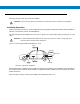
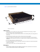
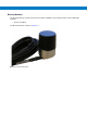
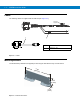
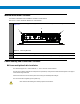
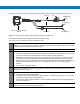

Table Of Contents
- Patents
- Warranty
- Legal Notice
- Revision History
- Introduction
- Configurations
- Chapter Descriptions
- Notational Conventions
- Related Documents
- Service Information
- Safety
- FCC Interference
- VML700 Description
- Installation
- Configuring and Monitoring the VML700
- Troubleshooting
- Using the VML700
- Specifications
- Reference

Modem Installation Procedure
Process 2-3 describes how to install the modem on a flat surface.
Cables Routing and Connection Procedure
DC Power and Ignition Cable Installation
The VML700 supports 12 V vehicle batteries, i.e. 13.8 V ±20% DC vehicle batteries.
The DC Power cable is equipped with 5-Ampere fuse (slow-blow). Verify that the vehicle electrical system can support
current values larger than that.
Connect the fuse in the red wire to the power source using the shortest practical length.
The unit is used with a negative ground system only.
Process 2-3
How to Install the Modem on a Flat Surface
1
Position the two mounting brackets (1) on both sides of the modem (2) and fasten using 4 screws each. See
Figure 2-7
.
Figure 2-7
Mounting Brackets
2
Locate the VML700 with the mounting brackets attached on the dedicated flat surface.
3
Centerpunch the marked spots and fix the modem in position using the self-drilling supplied screws.
1
1
2
Insert the fuse after making and carefully inspect all connections.