
User's Manual
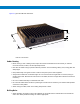
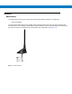
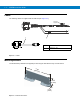
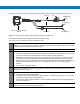

Table Of Contents
- Patents
- Warranty
- Legal Notice
- Revision History
- Introduction
- Configurations
- Chapter Descriptions
- Notational Conventions
- Related Documents
- Service Information
- Safety
- FCC Interference
- VML700 Description
- Installation
- Configuring and Monitoring the VML700
- Troubleshooting
- Using the VML700
- Specifications
- Reference

Figure 2-2 gives the VML700 dimensions.
VML700 - Dimensions
Cables Routing
•
Before running a wire or drilling a hole, inspect the vehicle and determine how and where you intend to
mount the antenna, modem, and the input/output device.
•
Plan wire and cable routing to provide maximum protection from overheating, battery acid, moving parts and
sharp edges.
•
Keep cables away from ignition circuits to reduce noise pickup in the radio equipment.
•
Verify that the cables are of sufficient length. Do not connect two short lengths with a connector; doing so
results in signal loss. Refrain from loose excess in the cables, but leave enough slack to allow reconnection if
necessary.
•
Do not run cables externally or underneath floor mats.
•
Do not locate cables where the driver or passengers can kick them or where they can interfere with operation
of the driver’s foot pedals.
•
When routing the cable, refrain from creating sharp bends or kinks.
Drilling Holes
•
Where possible, use existing holes in the bulkhead, the trunk wall and the channels above or beneath the
doors. Run cables parallel to existing car cables if appropriate.
1
1.71”
4.35cm
8.07”
20.5cm
7.87”
20cm