
User's Manual
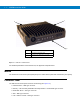
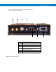
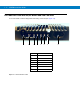

Table Of Contents
- Patents
- Warranty
- Legal Notice
- Revision History
- Introduction
- Configurations
- Chapter Descriptions
- Notational Conventions
- Related Documents
- Service Information
- Safety
- FCC Interference
- VML700 Description
- Installation
- Configuring and Monitoring the VML700
- Troubleshooting
- Using the VML700
- Specifications
- Reference

1 - 2 VML700 Installation Guide
Figure 1-1
VML700 - General View
For detailed specifications of the VML700 unit, see Appendix A: Specifications.
Modem
The modem has a Connectors panel (back panel) and a LED Indicator panel with On/Off button (front panel).
Connectors Panel
The VML700 Connectors panel consist of the following (see Figure 1-2):
•
LTE Main Rx/Tx – SMA type connector
•
Diversity – LTE secondary Rx/EVDO secondary Rx/WiFi – reverse SMA type connector
•
EVDO Main Rx/Tx – TNC type connector
•
GPS – SMC type connector
•
LAN – Ethernet 10/100 – RJ45 type connector
1 Modem
2 LED Indicator Panel (Front Panel)
3 Connectors Panel (Back Panel - not shown)
1
2
3