
Installation Manual

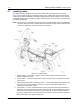


Table Of Contents
- Foreword
- Installation Requirements for Compliance with Radio Frequency (RF) Energy Exposure Safety Standards
- Table of Contents
- Mobile Radio Model Numbering Scheme
- Commercial Warranty
- Chapter 1 Introduction
- Chapter 2 Standard Configurations
- 2.1 Planning the Installation
- 2.2 Radio Mounting
- 2.2.1 Dash Mount with Trunnion
- 2.2.2 Remote Mount with Trunnion
- 2.2.2.1 Transceiver
- 2.2.2.2 Control Head and Remote Mount Cabling
- 2.2.3 Locking Kit (Optional)
- 2.3 Power Cable
- 2.4 Ignition Sense Cable
- 2.5 Antenna Installation
- 2.6 Speaker
- 2.7 Microphone Hang-Up Clip
- 2.8 Completing the Installation
- Chapter 3 Options and Accessories Installation
- Chapter 4 Motorcycle Radio Installation
- 4.1 Motorcycle Radio Description
- 4.2 Installation Overview
- 4.3 Installing the Universal Mounting Plate
- 4.4 Installing the Speaker and Control Head
- 4.4.1 Handlebar Installation with Speaker and Control Head Mounted Together
- 4.4.2 Fuel Tank Console Installation with Speaker and Control Head Mounted Together
- 4.4.3 Handlebar Installation with Speaker and Control Head Mounted Separately
- 4.4.4 Fuel Tank Console Installation with Speaker and Control Head Mounted Separately
- 4.5 Installing the Speaker
- 4.6 Installing the Microphone Hang-Up Clip
- 4.7 Installing Cables
- 4.8 Installing the Weather-Resistant Enclosure
- 4.9 Transceiver and Cabling Installation
- 4.10 Installing the Antenna
- 4.11 Installing the Emergency Switch Option
- 4.12 Installing the External Alarm Relay Option
- 4.13 Installing the Headset Accessory
- 4.14 Horn/Lights Wiring
- 4.15 Emergency Switch Wiring
- Chapter 5 Finishing the Installation: Cable Connection
- Appendix A Replacement Parts Ordering
- Glossary
- Index

September 17, 2004 6881098C38-O
4-14 Motorcycle Radio Installation: Transceiver and Cabling Installation
NOTE: Grounding through the power-supply cable is NOT sufficient. Whether the radio transceiver
is mounted to a carrier or the chassis itself, the transceiver MUST be properly grounded to
the motorcycle chassis. The ground strap supplied with the installation kit may have to be
used to ensure a good RF ground path from the radio transceiver to the motorcycle chassis.
4. Install the 3-foot ground strap on one of the front shock mounts. Route it through the cable-
routing hole and connect the other end to the motorcycle frame (see
Figure 4-7).
5. The diagram of the shock mount is shown loosely assembled. After the hex screws are
tightened, the rubber washers are compressed to fasten the weather- resistant enclosure
securely to the universal mounting plate.
6.
Figure 4-9 is an exploded view of the enclosure; it shows details that will help to understand
how the enclosure is mounted. After the enclosure is completely mounted, check for proper
ground connection–continuity between the antenna ground plane and the motorcycle frame.
4.9 Transceiver and Cabling Installation
After the weather-resistant enclosure has been installed, the radio chassis (transceiver) is installed in
the enclosure and then appropriate cables are connected. However, before the transceiver can be
installed, the cabling must be properly positioned in the enclosure.
4.9.1 Installing Cabling in the Enclosure
Position the cabling in the weather-resistant enclosure as follows:
1. Run the speaker, power, control-head, and ignition cables into the enclosure.
2. Lay the excess cable length between the radio mounting bosses in an S configuration as
shown in
Figure 4-8. Do not coil any excess cable. Use the supplied tie wraps to bundle cable
as shown.
NOTE: If the extra cable length is not sufficient to match the illustrated cable routing, then match the
illustration as closely as possible.
3. Connect the speaker cable to the accessory cable connector.
NOTE: The accessory-cable emergency connector is shipped with a shorting plug installed. The
headset connector is also shipped with a shorting plug installed. The plugs must remain in if
an emergency switch and/or headset is not used. If an emergency switch and/or headset is
used, remove the shorting plug(s) and discard.
4. Install the mounting plate in position on top of the cables installed above. Take care not to
damage or pinch the cables when securing the mounting plate in position.
NOTE: At this point, the control-head cable plug should be located at the forward end of the
enclosure, and the power-cable, speaker-cable, and accessory-cable plugs should be located
at the rear of the enclosure.
DO NOT connect the ground strap directly to the negative
battery post.
!
W A R N I N G
!