
Installation Manual

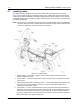


Table Of Contents
- Foreword
- Installation Requirements for Compliance with Radio Frequency (RF) Energy Exposure Safety Standards
- Table of Contents
- Mobile Radio Model Numbering Scheme
- Commercial Warranty
- Chapter 1 Introduction
- Chapter 2 Standard Configurations
- 2.1 Planning the Installation
- 2.2 Radio Mounting
- 2.2.1 Dash Mount with Trunnion
- 2.2.2 Remote Mount with Trunnion
- 2.2.2.1 Transceiver
- 2.2.2.2 Control Head and Remote Mount Cabling
- 2.2.3 Locking Kit (Optional)
- 2.3 Power Cable
- 2.4 Ignition Sense Cable
- 2.5 Antenna Installation
- 2.6 Speaker
- 2.7 Microphone Hang-Up Clip
- 2.8 Completing the Installation
- Chapter 3 Options and Accessories Installation
- Chapter 4 Motorcycle Radio Installation
- 4.1 Motorcycle Radio Description
- 4.2 Installation Overview
- 4.3 Installing the Universal Mounting Plate
- 4.4 Installing the Speaker and Control Head
- 4.4.1 Handlebar Installation with Speaker and Control Head Mounted Together
- 4.4.2 Fuel Tank Console Installation with Speaker and Control Head Mounted Together
- 4.4.3 Handlebar Installation with Speaker and Control Head Mounted Separately
- 4.4.4 Fuel Tank Console Installation with Speaker and Control Head Mounted Separately
- 4.5 Installing the Speaker
- 4.6 Installing the Microphone Hang-Up Clip
- 4.7 Installing Cables
- 4.8 Installing the Weather-Resistant Enclosure
- 4.9 Transceiver and Cabling Installation
- 4.10 Installing the Antenna
- 4.11 Installing the Emergency Switch Option
- 4.12 Installing the External Alarm Relay Option
- 4.13 Installing the Headset Accessory
- 4.14 Horn/Lights Wiring
- 4.15 Emergency Switch Wiring
- Chapter 5 Finishing the Installation: Cable Connection
- Appendix A Replacement Parts Ordering
- Glossary
- Index

September 17, 2004 6881098C38-O
4-12 Motorcycle Radio Installation: Installing Cables
4.7 Installing Cables
Five cables must be installed to interconnect the components of the radio system as shown in
Figure 4-6. The antenna cable is routed away from the other cables inside the enclosure’s hinged
cover. (See the antenna installation instructions shipped with the antenna option for more antenna-
routing information.) The four remaining cables, routed along the motorcycle frame, are described in
the following paragraphs.
NOTE: Removal of the fuel tank and seat from the motorcycle will facilitate routing the cables along
the frame. Motorcycles with consoles attached to fuel tanks require routing cables between
console and fuel tank. In this case the tank is not removed.
Figure 4-6. Cable Routing
1. Speaker Cable — runs from the speaker to the accessory-cable connector inside the
weather-resistant enclosure.
2. Control Cable — runs from the rear of the control head to the front of the transceiver inside
the enclosure.
3. Ignition (Red) Wire Portion of Accessory Cable — runs from the ignition fuse terminal of the
fuse box to the rear area inside the enclosure. The lug for attaching the ignition wire is
contained on the accessory cable.
4. Power Cable — The red, unterminated end runs from the positive terminal of the battery to
the power connector that plugs in the rear of the transceiver. Lugs for attaching the red and
black leads are contained in the motorcycle power-cable kit. The black, unterminated end
runs from a suitable motorcycle chassis ground to the power connector. DO NOT connect the
black lead directly to the negative battery post.