
Installation Manual


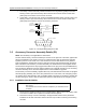


Table Of Contents
- Foreword
- Installation Requirements for Compliance with Radio Frequency (RF) Energy Exposure Safety Standards
- Table of Contents
- Mobile Radio Model Numbering Scheme
- Commercial Warranty
- Chapter 1 Introduction
- Chapter 2 Standard Configurations
- 2.1 Planning the Installation
- 2.2 Radio Mounting
- 2.2.1 Dash Mount with Trunnion
- 2.2.2 Remote Mount with Trunnion
- 2.2.2.1 Transceiver
- 2.2.2.2 Control Head and Remote Mount Cabling
- 2.2.3 Locking Kit (Optional)
- 2.3 Power Cable
- 2.4 Ignition Sense Cable
- 2.5 Antenna Installation
- 2.6 Speaker
- 2.7 Microphone Hang-Up Clip
- 2.8 Completing the Installation
- Chapter 3 Options and Accessories Installation
- Chapter 4 Motorcycle Radio Installation
- 4.1 Motorcycle Radio Description
- 4.2 Installation Overview
- 4.3 Installing the Universal Mounting Plate
- 4.4 Installing the Speaker and Control Head
- 4.4.1 Handlebar Installation with Speaker and Control Head Mounted Together
- 4.4.2 Fuel Tank Console Installation with Speaker and Control Head Mounted Together
- 4.4.3 Handlebar Installation with Speaker and Control Head Mounted Separately
- 4.4.4 Fuel Tank Console Installation with Speaker and Control Head Mounted Separately
- 4.5 Installing the Speaker
- 4.6 Installing the Microphone Hang-Up Clip
- 4.7 Installing Cables
- 4.8 Installing the Weather-Resistant Enclosure
- 4.9 Transceiver and Cabling Installation
- 4.10 Installing the Antenna
- 4.11 Installing the Emergency Switch Option
- 4.12 Installing the External Alarm Relay Option
- 4.13 Installing the Headset Accessory
- 4.14 Horn/Lights Wiring
- 4.15 Emergency Switch Wiring
- Chapter 5 Finishing the Installation: Cable Connection
- Appendix A Replacement Parts Ordering
- Glossary
- Index

6881098C38-O September 17, 2004
Options and Accessories Installation: Accessory Connector Assembly Details (P2) 3-13
1
As indicated for front and rear connectors
2
Pin function as a true “DCE” device according to EIA standard
1
EIA standard
2
The DB9 (female) serial port cable can be added to the P2 rear accessory cable (
Figure 3-6).
Note: TX to RX and RTS to CTS, not “same to same” (e.g., not TX to TX).
Table 3-4. Rear Connector and Front Connector Naming Schemes
J2 Pin Number J2 Pin Name
1
Pin Alternate Name
EIA Compatible Name at
Rear Connector J2
2
J2-4 UARTA_TX No change TX_DCE
J2-5 UARTA_RX No change RX_DCE
J2-10 UARTA_CTS Becomes RTS RTS_DCE
J2-11 UARTA_RTS Becomes CTS CTS_DCE
Table 3-5. How to Connect to a Computer
1
(DTE Device)
Radio Pin Direction
DB9 (Female) Serial Port
Connector
2
= DCE
Interface
DB9 (Male) Serial Port
Connector = DTE
Interface
Data Device Pin
Direction
Output TX_DCE = pin 2 pin 2 = RX_DTE Input
Input RX_DCE = pin 3 pin 3 = TX_DTE Output
Output RTS_DCE = pin 8 pin 8 = CTS_DTE Input
Input CTS_DCE = pin 7 pin 7 = RTS_DTE Output