
Installation Manual


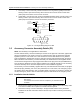


Table Of Contents
- Foreword
- Installation Requirements for Compliance with Radio Frequency (RF) Energy Exposure Safety Standards
- Table of Contents
- Mobile Radio Model Numbering Scheme
- Commercial Warranty
- Chapter 1 Introduction
- Chapter 2 Standard Configurations
- 2.1 Planning the Installation
- 2.2 Radio Mounting
- 2.2.1 Dash Mount with Trunnion
- 2.2.2 Remote Mount with Trunnion
- 2.2.2.1 Transceiver
- 2.2.2.2 Control Head and Remote Mount Cabling
- 2.2.3 Locking Kit (Optional)
- 2.3 Power Cable
- 2.4 Ignition Sense Cable
- 2.5 Antenna Installation
- 2.6 Speaker
- 2.7 Microphone Hang-Up Clip
- 2.8 Completing the Installation
- Chapter 3 Options and Accessories Installation
- Chapter 4 Motorcycle Radio Installation
- 4.1 Motorcycle Radio Description
- 4.2 Installation Overview
- 4.3 Installing the Universal Mounting Plate
- 4.4 Installing the Speaker and Control Head
- 4.4.1 Handlebar Installation with Speaker and Control Head Mounted Together
- 4.4.2 Fuel Tank Console Installation with Speaker and Control Head Mounted Together
- 4.4.3 Handlebar Installation with Speaker and Control Head Mounted Separately
- 4.4.4 Fuel Tank Console Installation with Speaker and Control Head Mounted Separately
- 4.5 Installing the Speaker
- 4.6 Installing the Microphone Hang-Up Clip
- 4.7 Installing Cables
- 4.8 Installing the Weather-Resistant Enclosure
- 4.9 Transceiver and Cabling Installation
- 4.10 Installing the Antenna
- 4.11 Installing the Emergency Switch Option
- 4.12 Installing the External Alarm Relay Option
- 4.13 Installing the Headset Accessory
- 4.14 Horn/Lights Wiring
- 4.15 Emergency Switch Wiring
- Chapter 5 Finishing the Installation: Cable Connection
- Appendix A Replacement Parts Ordering
- Glossary
- Index

6881098C38-O September 17, 2004
Options and Accessories Installation: Accessory Connector Assembly Details (P2) 3-11
3.5.5 Rear Accessory Jack Connection
Figure 3-9 shows the complete pin configuration for the J2 rear accessory jack, and Table 3-3
explains the functions of each of the pins.
Figure 3-9. Rear Accessory Jack Pin Configuration (J2) (Radio Side)
AUX
MIC
PTT
USB+
CTS
RTS
USB-
TXD
BUS-
BUS+
RXD
MAEPF-27619-O
1
7
8
14
13
20
21
26
EMERGENCY
GROUND
GROUND
RXFILT
AUDIO
MONITOR
RESET
SPKR-
SWB+
SPKR+
VIP
OUT1
VIP
OUT2
ONE
WIRE
IGNITION
BUSY
USB
PWR
CHAN
ACT