
Installation Manual


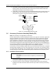


Table Of Contents
- Foreword
- Installation Requirements for Compliance with Radio Frequency (RF) Energy Exposure Safety Standards
- Table of Contents
- Mobile Radio Model Numbering Scheme
- Commercial Warranty
- Chapter 1 Introduction
- Chapter 2 Standard Configurations
- 2.1 Planning the Installation
- 2.2 Radio Mounting
- 2.2.1 Dash Mount with Trunnion
- 2.2.2 Remote Mount with Trunnion
- 2.2.2.1 Transceiver
- 2.2.2.2 Control Head and Remote Mount Cabling
- 2.2.3 Locking Kit (Optional)
- 2.3 Power Cable
- 2.4 Ignition Sense Cable
- 2.5 Antenna Installation
- 2.6 Speaker
- 2.7 Microphone Hang-Up Clip
- 2.8 Completing the Installation
- Chapter 3 Options and Accessories Installation
- Chapter 4 Motorcycle Radio Installation
- 4.1 Motorcycle Radio Description
- 4.2 Installation Overview
- 4.3 Installing the Universal Mounting Plate
- 4.4 Installing the Speaker and Control Head
- 4.4.1 Handlebar Installation with Speaker and Control Head Mounted Together
- 4.4.2 Fuel Tank Console Installation with Speaker and Control Head Mounted Together
- 4.4.3 Handlebar Installation with Speaker and Control Head Mounted Separately
- 4.4.4 Fuel Tank Console Installation with Speaker and Control Head Mounted Separately
- 4.5 Installing the Speaker
- 4.6 Installing the Microphone Hang-Up Clip
- 4.7 Installing Cables
- 4.8 Installing the Weather-Resistant Enclosure
- 4.9 Transceiver and Cabling Installation
- 4.10 Installing the Antenna
- 4.11 Installing the Emergency Switch Option
- 4.12 Installing the External Alarm Relay Option
- 4.13 Installing the Headset Accessory
- 4.14 Horn/Lights Wiring
- 4.15 Emergency Switch Wiring
- Chapter 5 Finishing the Installation: Cable Connection
- Appendix A Replacement Parts Ordering
- Glossary
- Index

September 17, 2004 6881098C38-O
3-10 Options and Accessories Installation: Accessory Connector Assembly Details (P2)
5. Squeeze the covers together bending the wires in the strain-relief features. You may need a
pair of pliers to seat the assembly covers.
6. Once the covers are fully seated, fasten them with the cover screws. Tighten the screws
firmly but do not over-tighten them. Be sure none of the wires are pinched.
7. Reattach the accessory connector assembly to the back of the radio and fasten it by finger-
tightening the jackscrews to prevent any loosening.
3.5.4 Adapter Cable
If you are planning on installing an XTL 5000 radio as a replacement for an ASTRO Spectra radio,
the following adapter cables are available:
Use the HKN6158_ audio adapter kit cable if your vehicle was formerly wired for an ASTRO Spectra
or ASTRO Spectra Plus radio, and used the rear cable pins as shown in
Figure 3-7:
Figure 3-7. Rear Accessory Connector Audio Configuration
Use the HKN6159_ data adapter kit cable if your vehicle was formerly wired for an ASTRO Spectra
or ASTRO Spectra Plus radio, and used the rear cable pins as shown in
Figure 3-8:
Figure 3-8. Rear Accessory Connector Data Configuration
It is highly recommended that you attach the correct adapter. Installing the wrong adapter may cause
damage to the data communication circuitry inside your radio. If you are unsure of the pinout of your
former wiring harness, please consult your ASTRO radio installation technician.
HKN6158_ Cable, Audio Adapter Kit
HKN6159_ Cable, Data Adapter Kit
VIPOUT2
IGNITION
SPKR
LO-
N.C.
GND SPKR
HI+
SWB+
EMER
N.C.VIPOUT1
MICHI
N.C.
PTT
DISC.
AUD
N.C.
54
3
21
9
1011121314
15
768
VIPOUT2
IGNITION
SPKR
LO-
CTS-ASTRO
RTS_DCE
DIG
GND
SPKR
HI+
SWB+
EMER
BUS-
VIPOUT1
RTS-ASTRO
CTS_DCE
BUSY
TX-ASTRO
RX_DCE
RX-ASTRO
TX_DCE
BUS+
54
3
21
9
1011121314
15
768