
Installation Manual


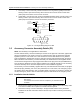


Table Of Contents
- Foreword
- Installation Requirements for Compliance with Radio Frequency (RF) Energy Exposure Safety Standards
- Table of Contents
- Mobile Radio Model Numbering Scheme
- Commercial Warranty
- Chapter 1 Introduction
- Chapter 2 Standard Configurations
- 2.1 Planning the Installation
- 2.2 Radio Mounting
- 2.2.1 Dash Mount with Trunnion
- 2.2.2 Remote Mount with Trunnion
- 2.2.2.1 Transceiver
- 2.2.2.2 Control Head and Remote Mount Cabling
- 2.2.3 Locking Kit (Optional)
- 2.3 Power Cable
- 2.4 Ignition Sense Cable
- 2.5 Antenna Installation
- 2.6 Speaker
- 2.7 Microphone Hang-Up Clip
- 2.8 Completing the Installation
- Chapter 3 Options and Accessories Installation
- Chapter 4 Motorcycle Radio Installation
- 4.1 Motorcycle Radio Description
- 4.2 Installation Overview
- 4.3 Installing the Universal Mounting Plate
- 4.4 Installing the Speaker and Control Head
- 4.4.1 Handlebar Installation with Speaker and Control Head Mounted Together
- 4.4.2 Fuel Tank Console Installation with Speaker and Control Head Mounted Together
- 4.4.3 Handlebar Installation with Speaker and Control Head Mounted Separately
- 4.4.4 Fuel Tank Console Installation with Speaker and Control Head Mounted Separately
- 4.5 Installing the Speaker
- 4.6 Installing the Microphone Hang-Up Clip
- 4.7 Installing Cables
- 4.8 Installing the Weather-Resistant Enclosure
- 4.9 Transceiver and Cabling Installation
- 4.10 Installing the Antenna
- 4.11 Installing the Emergency Switch Option
- 4.12 Installing the External Alarm Relay Option
- 4.13 Installing the Headset Accessory
- 4.14 Horn/Lights Wiring
- 4.15 Emergency Switch Wiring
- Chapter 5 Finishing the Installation: Cable Connection
- Appendix A Replacement Parts Ordering
- Glossary
- Index

6881098C38-O September 17, 2004
Options and Accessories Installation: Accessory Connector Assembly Details (P2) 3-9
3.5.3 Disassembly and Assembly
3.5.3.1 Disassembly
1. Disconnect the negative terminal from the vehicle’s battery. Make sure that the battery cable
is secured such that it will not power the vehicle’s electrical system. See
Figure 3-6.
2. Unscrew both jackscrews completely.
3. Pull the accessory connector assembly out from the radio.
4. Loosen both cover screws, but do not remove them completely.
5. Pull the jackscrews away from the plug and hold them back.
6. Pry apart the accessory connector assembly covers.
7. Attach any new wire to its proper location by pushing in the male terminal. When you hear a
pop, the wire is engaged. To verify that the wire is engaged, tug gently on the wire and be
sure it does not come out. Do not overload the wire: severe damage will result to the plug.
3.5.3.2 Assembly
1. Place the plug in one cover. Be sure that the flange of the plug is in the slot of the cover. See
Figure 3-6.
2. Push the jackscrew through the plug to hold it in.
3. Position each wire across the strain-relief features in the cover. Avoid damaging loads on the
plug by allowing some slack in each wire in the accessory connector assembly’s wire
chamber.
4. Place the second cover onto the plug. Be sure that the flange is protruding through both
covers.
Figure 3-6. Exploded View of Accessory Connector Assembly (P2)