
Installation Manual


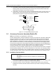


Table Of Contents
- Foreword
- Installation Requirements for Compliance with Radio Frequency (RF) Energy Exposure Safety Standards
- Table of Contents
- Mobile Radio Model Numbering Scheme
- Commercial Warranty
- Chapter 1 Introduction
- Chapter 2 Standard Configurations
- 2.1 Planning the Installation
- 2.2 Radio Mounting
- 2.2.1 Dash Mount with Trunnion
- 2.2.2 Remote Mount with Trunnion
- 2.2.2.1 Transceiver
- 2.2.2.2 Control Head and Remote Mount Cabling
- 2.2.3 Locking Kit (Optional)
- 2.3 Power Cable
- 2.4 Ignition Sense Cable
- 2.5 Antenna Installation
- 2.6 Speaker
- 2.7 Microphone Hang-Up Clip
- 2.8 Completing the Installation
- Chapter 3 Options and Accessories Installation
- Chapter 4 Motorcycle Radio Installation
- 4.1 Motorcycle Radio Description
- 4.2 Installation Overview
- 4.3 Installing the Universal Mounting Plate
- 4.4 Installing the Speaker and Control Head
- 4.4.1 Handlebar Installation with Speaker and Control Head Mounted Together
- 4.4.2 Fuel Tank Console Installation with Speaker and Control Head Mounted Together
- 4.4.3 Handlebar Installation with Speaker and Control Head Mounted Separately
- 4.4.4 Fuel Tank Console Installation with Speaker and Control Head Mounted Separately
- 4.5 Installing the Speaker
- 4.6 Installing the Microphone Hang-Up Clip
- 4.7 Installing Cables
- 4.8 Installing the Weather-Resistant Enclosure
- 4.9 Transceiver and Cabling Installation
- 4.10 Installing the Antenna
- 4.11 Installing the Emergency Switch Option
- 4.12 Installing the External Alarm Relay Option
- 4.13 Installing the Headset Accessory
- 4.14 Horn/Lights Wiring
- 4.15 Emergency Switch Wiring
- Chapter 5 Finishing the Installation: Cable Connection
- Appendix A Replacement Parts Ordering
- Glossary
- Index

6881098C38-O September 17, 2004
Options and Accessories Installation: Accessory Connector Assembly Details (P2) 3-7
1. Horn Relay—Connect the relay contacts across the horn ring switch, typically found in the
steering column. Open the accessory cable connector and connect the two control wires
(male pins) into locations 12 and 4 of the connector.
2. Lights Relay—Connect the relay across the headlamp ON/OFF switch, typically found in the
steering column. Open the accessory cable connector and connect the two control wires
(male pins) into locations 3 and 4 of the accessory connector.
Figure 3-5. Horn/Light Wiring Diagram for W3
3.5 Accessory Connector Assembly Details (P2)
NOTE: This assembly is not applicable for 100W radios.
The XTL 5000 accessory connector assembly is mounted on the right rear of the radio, opposite the
antenna and adjacent to the power connector. It is fastened to the radio via jackscrews and held
together by the two cover screws. It is a multi-functional connector that allows for many different
types of adaptations. All approved accessory wires are securely strain-relieved through the exiting
slots at the back of the accessory connector assembly. The terminations that are supplied with all
accessories are designed to be fully engaged and locked into the plug connector (P/N 6680163F01).
They can also be detached for service with the assistance of a terminal removal tool. The accessory
connector assembly can be serviced multiple times for future installation upgrades.
The accessory connector assembly, supplied with every XTL 5000 dash-mounted radio, is equipped
with a 26-pin plug assembly, two covers, two jackscrews, two cover screws, one emergency jumper,
one ignition sense cable assembly, and one speaker pigtail. The jumper is provided to complete the
circuit for emergency mode. If this circuit becomes open, the radio will be set to emergency mode.
3.5.1 Installation into the Vehicle
1. Disconnect the negative terminal from the vehicle’s battery. Make sure that the battery cable
is secured such that it will not power the vehicle’s electrical system.
2. Place the accessory connector assembly in the approximate location for the permanent
installation of the radio. Allocate a sufficient service loop for ease of removing and servicing
the radio.
CAUTION Before installing any electrical equipment, check the vehicle manufacturer’s
user manual.
The installation of this device should be completed by an authorized servicer
or installer.
123
4
56
7
8
11
12
1314
10 915
SWB+
VIP OUT 2 (LIGHTS)
VIP OUT 1 (HORN)
CONNECT
ACROSS HORN
RING SWITCH
CONNECT
ACROSS HEAD
LAMP SWITCH
SPST
N.O.
RELAY
12V COIL
12V COIL
VIP OUT 1
SWB+
VIP OUT 2
SPST
N.O.
RELAY
ACCESSORIES
CONNECTOR
PIN 12
PIN 4
PIN 3