
Installation Manual


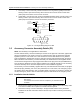


Table Of Contents
- Foreword
- Installation Requirements for Compliance with Radio Frequency (RF) Energy Exposure Safety Standards
- Table of Contents
- Mobile Radio Model Numbering Scheme
- Commercial Warranty
- Chapter 1 Introduction
- Chapter 2 Standard Configurations
- 2.1 Planning the Installation
- 2.2 Radio Mounting
- 2.2.1 Dash Mount with Trunnion
- 2.2.2 Remote Mount with Trunnion
- 2.2.2.1 Transceiver
- 2.2.2.2 Control Head and Remote Mount Cabling
- 2.2.3 Locking Kit (Optional)
- 2.3 Power Cable
- 2.4 Ignition Sense Cable
- 2.5 Antenna Installation
- 2.6 Speaker
- 2.7 Microphone Hang-Up Clip
- 2.8 Completing the Installation
- Chapter 3 Options and Accessories Installation
- Chapter 4 Motorcycle Radio Installation
- 4.1 Motorcycle Radio Description
- 4.2 Installation Overview
- 4.3 Installing the Universal Mounting Plate
- 4.4 Installing the Speaker and Control Head
- 4.4.1 Handlebar Installation with Speaker and Control Head Mounted Together
- 4.4.2 Fuel Tank Console Installation with Speaker and Control Head Mounted Together
- 4.4.3 Handlebar Installation with Speaker and Control Head Mounted Separately
- 4.4.4 Fuel Tank Console Installation with Speaker and Control Head Mounted Separately
- 4.5 Installing the Speaker
- 4.6 Installing the Microphone Hang-Up Clip
- 4.7 Installing Cables
- 4.8 Installing the Weather-Resistant Enclosure
- 4.9 Transceiver and Cabling Installation
- 4.10 Installing the Antenna
- 4.11 Installing the Emergency Switch Option
- 4.12 Installing the External Alarm Relay Option
- 4.13 Installing the Headset Accessory
- 4.14 Horn/Lights Wiring
- 4.15 Emergency Switch Wiring
- Chapter 5 Finishing the Installation: Cable Connection
- Appendix A Replacement Parts Ordering
- Glossary
- Index

September 22, 2004 6881098C38-O
3-6 Options and Accessories Installation: Remote-Mount Accessory Installations for W3 Model
3.4 Remote-Mount Accessory Installations for W3 Model
Accessories for the W3 remote mount handheld control head are connected through the J3
connector located in the remote cable assembly. It requires a different P3 connector (supplied). This
P3 connector is a 15 pin D-sub (see
Figure 2-11 in Chapter 2), unlike the 26-pin accessory connector
assembly (see Figure 3-9). The terminals that are required are the same for both. Therefore all
accessories will be compatible with all XTL 5000 radios.
1. Remove P3 connector from remote harness by pulling it out.
2. Remove the two screws holding the 15-pin D-sub.
3. Loosen the strain-relief screw located adjacent to the wire-exiting hole in the back of the
connector cover.
4. Extract the D-sub by pushing the wires into the cover.
5. Route the accessory wires through the hole and insert the male pin into the appropriate
location. A tool is available to remove the male terminals if service is required. (
See Appendix
A: Replacement Parts Ordering
.)
6. While holding the cover, pull each wire to achieve a uniform slack, then pull all wires until the
D-sub is seated against the cover.
7. Reattach the two screws to secure the D-sub, and tighten them appropriately.
8. Tighten the strain-relief screw adjacent to the wire outlet hole appropriately.
9. Reconnect the P3 connector onto the remote cable assembly.
10. Secure all wires using tie straps or electrical tape to prevent damage or shorting.
3.4.1 MDC Emergency Pushbutton or Footswitch Installation for W3 with Remote
Cable Assembly
Mount the footswitch using the hardware that comes with the kit. Open the accessory cable
connector housing; remove the jumper wire. Connect the emergency switch wires to pins 2 and 8
(see Figure 3-4). Close the connector housing; route the finished cable from the switch location to
the J3 connector location.
Figure 3-4. Emergency Switch Wiring Diagram for W3
3.4.2 Horn and Lights (External Alarms) Relays Installation for W3 with Remote
Cable Assembly
For installations that use the horn/lights option, select a suitable location for mounting (normally
under the dash) and, referring to Figure 3-5, perform the following procedure:
NOTE: The handheld control head can have a horn or light option, but not both. Control wires for
either option should be connected to pins 12 and 4 of the accessory connector.
ACCESSORIES
CONNECTOR
PIN 2
PIN 8
123
4
56
7
8
11
12
1314
10 915
NOTE 1
SPST NORMALLY CLOSED
EMERGENCY SWITCH
NOTE 1: REMOVE BLACK JUMPER WIRE INSIDE
ACCESSORY CONNECTOR HOUSING.
INSERT WIRES FROM EMERGENCY SWITCH
DIG GND
EMER