
Installation Manual


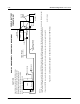
Table Of Contents
- Foreword
- Installation Requirements for Compliance with Radio Frequency (RF) Energy Exposure Safety Standards
- Table of Contents
- Mobile Radio Model Numbering Scheme
- Commercial Warranty
- Chapter 1 Introduction
- Chapter 2 Standard Configurations
- 2.1 Planning the Installation
- 2.2 Radio Mounting
- 2.2.1 Dash Mount with Trunnion
- 2.2.2 Remote Mount with Trunnion
- 2.2.2.1 Transceiver
- 2.2.2.2 Control Head and Remote Mount Cabling
- 2.2.3 Locking Kit (Optional)
- 2.3 Power Cable
- 2.4 Ignition Sense Cable
- 2.5 Antenna Installation
- 2.6 Speaker
- 2.7 Microphone Hang-Up Clip
- 2.8 Completing the Installation
- Chapter 3 Options and Accessories Installation
- Chapter 4 Motorcycle Radio Installation
- 4.1 Motorcycle Radio Description
- 4.2 Installation Overview
- 4.3 Installing the Universal Mounting Plate
- 4.4 Installing the Speaker and Control Head
- 4.4.1 Handlebar Installation with Speaker and Control Head Mounted Together
- 4.4.2 Fuel Tank Console Installation with Speaker and Control Head Mounted Together
- 4.4.3 Handlebar Installation with Speaker and Control Head Mounted Separately
- 4.4.4 Fuel Tank Console Installation with Speaker and Control Head Mounted Separately
- 4.5 Installing the Speaker
- 4.6 Installing the Microphone Hang-Up Clip
- 4.7 Installing Cables
- 4.8 Installing the Weather-Resistant Enclosure
- 4.9 Transceiver and Cabling Installation
- 4.10 Installing the Antenna
- 4.11 Installing the Emergency Switch Option
- 4.12 Installing the External Alarm Relay Option
- 4.13 Installing the Headset Accessory
- 4.14 Horn/Lights Wiring
- 4.15 Emergency Switch Wiring
- Chapter 5 Finishing the Installation: Cable Connection
- Appendix A Replacement Parts Ordering
- Glossary
- Index

September 17, 2004 6881098C38-O
2-20 Standard Configurations: Power Cable
RADIOCOMPARTMENT=OPERATORCOMPARTMENT
VEHICLEBATTERY
COMPARTMENT
Agoodchassisconnectionviatheblackprimary
powercableisessentialforradiooperationand
topreventdamagetotheradioandcablekit.
Connectiontothevehicleframeisdesirable.
VEHICLE
BATTERY
15AOR20A
FUSE
PARTOF
VEHICLE
WIRING
VEHICLE
IGNITIONSWITCH
ON/ACC
GROMMET
RADIOPOWERCABLE
(RED/BATTERYHOT)
RADIOIGNITION
CABLE(thinRED)
SPEAKER
3AOR4AFUSE
MICROPHONE
RADIOPOWERCABLE(BLK/GROUND)
RADIO
(-)
(+)
CAUTION
MAEPF-27646-O
Rearconnector
CH
SEENOTE
NOTE:
Caution:ifyouchoosetoconnecttheradio'sIGNITIONlinedirectlytothecar'sbattery,excessuseoftheradiowhenthecar'signitionisnotrunning(i.e.alternatorrunning)
couldresultinaslowdischargeofthecar'sbattery.Thisconfigurationallowstheradiotooperatewiththecar'signitionswitchONorOFF.
Iftheradio'sIGNITIONlineiswiredtothecar'signitionswitch,theradiowillonlyfunctionwhenthecar'signitionswitchisturnedON.
Figure 2-29. Cabling Interconnect Diagram for Dash Mount (Cannot Be Used for 100W Radios)