
Installation Manual


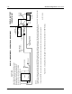
Table Of Contents
- Foreword
- Installation Requirements for Compliance with Radio Frequency (RF) Energy Exposure Safety Standards
- Table of Contents
- Mobile Radio Model Numbering Scheme
- Commercial Warranty
- Chapter 1 Introduction
- Chapter 2 Standard Configurations
- 2.1 Planning the Installation
- 2.2 Radio Mounting
- 2.2.1 Dash Mount with Trunnion
- 2.2.2 Remote Mount with Trunnion
- 2.2.2.1 Transceiver
- 2.2.2.2 Control Head and Remote Mount Cabling
- 2.2.3 Locking Kit (Optional)
- 2.3 Power Cable
- 2.4 Ignition Sense Cable
- 2.5 Antenna Installation
- 2.6 Speaker
- 2.7 Microphone Hang-Up Clip
- 2.8 Completing the Installation
- Chapter 3 Options and Accessories Installation
- Chapter 4 Motorcycle Radio Installation
- 4.1 Motorcycle Radio Description
- 4.2 Installation Overview
- 4.3 Installing the Universal Mounting Plate
- 4.4 Installing the Speaker and Control Head
- 4.4.1 Handlebar Installation with Speaker and Control Head Mounted Together
- 4.4.2 Fuel Tank Console Installation with Speaker and Control Head Mounted Together
- 4.4.3 Handlebar Installation with Speaker and Control Head Mounted Separately
- 4.4.4 Fuel Tank Console Installation with Speaker and Control Head Mounted Separately
- 4.5 Installing the Speaker
- 4.6 Installing the Microphone Hang-Up Clip
- 4.7 Installing Cables
- 4.8 Installing the Weather-Resistant Enclosure
- 4.9 Transceiver and Cabling Installation
- 4.10 Installing the Antenna
- 4.11 Installing the Emergency Switch Option
- 4.12 Installing the External Alarm Relay Option
- 4.13 Installing the Headset Accessory
- 4.14 Horn/Lights Wiring
- 4.15 Emergency Switch Wiring
- Chapter 5 Finishing the Installation: Cable Connection
- Appendix A Replacement Parts Ordering
- Glossary
- Index

September 17, 2004 6881098C38-O
2-18 Standard Configurations
2.2.3 Locking Kit (Optional)
2.2.3.1 All Radios Except 100W
If an optional locking kit is used (shown in
Figure 2-26), position the lock bottom housing on the
trunnion before installing the radio mounting screws. Then slip the top lock housing on and remove
the key. You can install the lock on either side of the radio, and by rotating it 180°, you can also install
it on dash installations.
Figure 2-26. Locking Kit (Optional) (Cannot Be Used for 100W Radios)
2.2.3.2 100W Radios
An integral lock is included in the quick release trunnion (HLN6909_). The use of this lock is required
for proper operation (see
Figure 2-27).
Figure 2-27. Lock Supplied with 100W Quick Release Trunnion
2.3 Power Cable
Route the red radio power cable from the radio to the vehicle’s battery compartment, using accepted
industry methods and standards. Be sure to grommet the firewall hole to protect the cable. Remove
the 15-amp (P/N 6580283E06) or 20-amp (P/N 6580283E07) fuse from the fuseholder and connect
the red lead of the radio power cable to the positive battery terminal using the hardware provided as
shown in
Figure 2-28 and Figure 2-29. Connect the black lead to a convenient solid chassis ground
point. DO NOT connect the black lead directly to the battery’s negative terminal.
Existing
Mounting
Screw
Lock
Lock
Housing
HLN6372_ Locking Kit