
Installation Manual


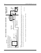
Table Of Contents
- Foreword
- Installation Requirements for Compliance with Radio Frequency (RF) Energy Exposure Safety Standards
- Table of Contents
- Mobile Radio Model Numbering Scheme
- Commercial Warranty
- Chapter 1 Introduction
- Chapter 2 Standard Configurations
- 2.1 Planning the Installation
- 2.2 Radio Mounting
- 2.2.1 Dash Mount with Trunnion
- 2.2.2 Remote Mount with Trunnion
- 2.2.2.1 Transceiver
- 2.2.2.2 Control Head and Remote Mount Cabling
- 2.2.3 Locking Kit (Optional)
- 2.3 Power Cable
- 2.4 Ignition Sense Cable
- 2.5 Antenna Installation
- 2.6 Speaker
- 2.7 Microphone Hang-Up Clip
- 2.8 Completing the Installation
- Chapter 3 Options and Accessories Installation
- Chapter 4 Motorcycle Radio Installation
- 4.1 Motorcycle Radio Description
- 4.2 Installation Overview
- 4.3 Installing the Universal Mounting Plate
- 4.4 Installing the Speaker and Control Head
- 4.4.1 Handlebar Installation with Speaker and Control Head Mounted Together
- 4.4.2 Fuel Tank Console Installation with Speaker and Control Head Mounted Together
- 4.4.3 Handlebar Installation with Speaker and Control Head Mounted Separately
- 4.4.4 Fuel Tank Console Installation with Speaker and Control Head Mounted Separately
- 4.5 Installing the Speaker
- 4.6 Installing the Microphone Hang-Up Clip
- 4.7 Installing Cables
- 4.8 Installing the Weather-Resistant Enclosure
- 4.9 Transceiver and Cabling Installation
- 4.10 Installing the Antenna
- 4.11 Installing the Emergency Switch Option
- 4.12 Installing the External Alarm Relay Option
- 4.13 Installing the Headset Accessory
- 4.14 Horn/Lights Wiring
- 4.15 Emergency Switch Wiring
- Chapter 5 Finishing the Installation: Cable Connection
- Appendix A Replacement Parts Ordering
- Glossary
- Index

6881098C38-O September 17, 2004
Standard Configurations: Radio Mounting 2-17
• Slide the plastic insulator fuseholder over the end of the wire that is connected to the cable kit.
Insert the stripped end of that wire into one of the metal fuse clips, and crimp it closed onto the
exposed wire. Solder it for a better electrical contact.
• On the end of the loose wire, repeat the above crimping and soldering process with the remain-
ing metal fuse clip.
• Temporarily, install the fuse into the fuse clips onto both sides of the fuse. Slide the spring over
the remaining loose end of the wire. The spring should be followed by the plastic insulator fuse-
holder oriented as shown in
Figure 2-25. Slide the plastic insulator fuse holder together, by first
making sure the spring slips inside the plastic insulator fuseholder cap. Now, twist the fusehold-
ers until they lock together. After assembly proves successful, remove the fuses until instructed
to install them later.
With the spring and plastic insulator fuseholder cap still in place on the loose portion of the wires
(orange and green), insert the stripped end of the wire into the spade or ring tongue lug. Crimp and
solder the lug as was done on the metal fuse clips above.
2.2.2.2.4.1 Transmitter Control Power Lead (Orange)
Connect the orange lead to the ignition switch (recommended) or directly to the battery hot supply
(see
Figure 2-28).
2.2.2.2.4.2 Receiver Control Power Lead (Green)
Connect the green lead to the positive battery terminal (recommended) or the ignition switch (see
Figure 2-28).
Table 2-2. Fuse Assembly for Orange and Green Leads Parts List
Motorola Part Number Description
1482882A01 Insulator, Fuseholder Body
1482883A01 Insulator, Fuseholder Cap
2900136968 Lug
2900824456 Lug, Ring Tongue
2900865065 Lug, Ring Tongue
4182885A01 Spring, Compression; Fuse
4282884Q01 Clip, Fuse
6500020404 Fuse, 3-Amp 250V (Qty. 2)