
Installation Manual


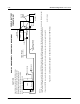
Table Of Contents
- Foreword
- Installation Requirements for Compliance with Radio Frequency (RF) Energy Exposure Safety Standards
- Table of Contents
- Mobile Radio Model Numbering Scheme
- Commercial Warranty
- Chapter 1 Introduction
- Chapter 2 Standard Configurations
- 2.1 Planning the Installation
- 2.2 Radio Mounting
- 2.2.1 Dash Mount with Trunnion
- 2.2.2 Remote Mount with Trunnion
- 2.2.2.1 Transceiver
- 2.2.2.2 Control Head and Remote Mount Cabling
- 2.2.3 Locking Kit (Optional)
- 2.3 Power Cable
- 2.4 Ignition Sense Cable
- 2.5 Antenna Installation
- 2.6 Speaker
- 2.7 Microphone Hang-Up Clip
- 2.8 Completing the Installation
- Chapter 3 Options and Accessories Installation
- Chapter 4 Motorcycle Radio Installation
- 4.1 Motorcycle Radio Description
- 4.2 Installation Overview
- 4.3 Installing the Universal Mounting Plate
- 4.4 Installing the Speaker and Control Head
- 4.4.1 Handlebar Installation with Speaker and Control Head Mounted Together
- 4.4.2 Fuel Tank Console Installation with Speaker and Control Head Mounted Together
- 4.4.3 Handlebar Installation with Speaker and Control Head Mounted Separately
- 4.4.4 Fuel Tank Console Installation with Speaker and Control Head Mounted Separately
- 4.5 Installing the Speaker
- 4.6 Installing the Microphone Hang-Up Clip
- 4.7 Installing Cables
- 4.8 Installing the Weather-Resistant Enclosure
- 4.9 Transceiver and Cabling Installation
- 4.10 Installing the Antenna
- 4.11 Installing the Emergency Switch Option
- 4.12 Installing the External Alarm Relay Option
- 4.13 Installing the Headset Accessory
- 4.14 Horn/Lights Wiring
- 4.15 Emergency Switch Wiring
- Chapter 5 Finishing the Installation: Cable Connection
- Appendix A Replacement Parts Ordering
- Glossary
- Index

September 17, 2004 6881098C38-O
2-16 Standard Configurations: Radio Mounting
If either wire is to be connected in the vehicle’s battery compartment, pass the end of the wire
through the same firewall hole that the red radio power cable uses. At this point, install a fuseholder
assembly in both wires (see Figure 2-25); the following procedures apply to both green and orange
wires:
Figure 2-25. Fuseholder Assembly for Orange and Green Control Cables
• A fuse will need to be placed in-line for both the orange and green wires; consideration should
be taken when deciding where to place the fuses so that they are easy to inspect. However,
they should also be placed as close as possible to the battery or the vehicle’s ignition switch
terminal.
• After choosing the fuse locations, the fuse receptacles need to be installed. This is done by cut-
ting the wire at the chosen location and stripping 1/8-inch of insulation on all loose ends. Make
sure the wire will reach its intended destination.
CAUTION: DO NOT connect either lead to the ungrounded
terminal of the battery until you have finalized the installation and
have been instructed to do so.
Table 2-1. Radio Functions Connections
Conductor Green Orange Green Orange Green Orange
Connected to battery X X X
Connected to ignition
switch
XXX
Ignition switch controls No ignition switch control Transmitter ignition switch
controlled
Complete radio ignition
switch controlled
In any application, trim and strip wires. Crimp on ring lug for battery connections. For ignition switch connections, crimp
on ring or spade lug (whichever is required).
!
C a u t i o n
SPADE OR RING
TONGUE LUG
(RING TONGUE
LUG SHOWN)
PLASTIC INSULATOR
FUSE HOLDER CAP
METAL FUSE
CLIPS CRIMP
AND SOLDER
TO WIRE
TO CONTROL
HEAD
SPRING
FUSE
PLASTIC INSULATOR
FUSE HOLDER
MAEPF-21361-O