
Installation Manual


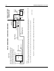
Table Of Contents
- Foreword
- Installation Requirements for Compliance with Radio Frequency (RF) Energy Exposure Safety Standards
- Table of Contents
- Mobile Radio Model Numbering Scheme
- Commercial Warranty
- Chapter 1 Introduction
- Chapter 2 Standard Configurations
- 2.1 Planning the Installation
- 2.2 Radio Mounting
- 2.2.1 Dash Mount with Trunnion
- 2.2.2 Remote Mount with Trunnion
- 2.2.2.1 Transceiver
- 2.2.2.2 Control Head and Remote Mount Cabling
- 2.2.3 Locking Kit (Optional)
- 2.3 Power Cable
- 2.4 Ignition Sense Cable
- 2.5 Antenna Installation
- 2.6 Speaker
- 2.7 Microphone Hang-Up Clip
- 2.8 Completing the Installation
- Chapter 3 Options and Accessories Installation
- Chapter 4 Motorcycle Radio Installation
- 4.1 Motorcycle Radio Description
- 4.2 Installation Overview
- 4.3 Installing the Universal Mounting Plate
- 4.4 Installing the Speaker and Control Head
- 4.4.1 Handlebar Installation with Speaker and Control Head Mounted Together
- 4.4.2 Fuel Tank Console Installation with Speaker and Control Head Mounted Together
- 4.4.3 Handlebar Installation with Speaker and Control Head Mounted Separately
- 4.4.4 Fuel Tank Console Installation with Speaker and Control Head Mounted Separately
- 4.5 Installing the Speaker
- 4.6 Installing the Microphone Hang-Up Clip
- 4.7 Installing Cables
- 4.8 Installing the Weather-Resistant Enclosure
- 4.9 Transceiver and Cabling Installation
- 4.10 Installing the Antenna
- 4.11 Installing the Emergency Switch Option
- 4.12 Installing the External Alarm Relay Option
- 4.13 Installing the Headset Accessory
- 4.14 Horn/Lights Wiring
- 4.15 Emergency Switch Wiring
- Chapter 5 Finishing the Installation: Cable Connection
- Appendix A Replacement Parts Ordering
- Glossary
- Index

6881098C38-O September 17, 2004
Standard Configurations: Radio Mounting 2-15
2.2.2.2.2 Remote W3 Model Control Head Installation
Figure 2-24 shows the W3 control head model.
Figure 2-24. W3 Control Head
For the remote handheld control unit, mount the control cable with the screws provided. Connect the
control cable as shown in
Figure 2-11 or Figure 2-12. Connect the speaker to the accessory cable
harness.
2.2.2.2.3 Remote Radio Control Cable Installation
The radio control cable should go from the rear of the control head to the radio. Route the cables in
the vehicle’s wiring troughs (where available) or route the cables where they are protected from
pinching, sharp edges, or crushing. One suggested route is along one side of the driveshaft hump
under the carpet. Use grommets in any holes where the cable passes through metal panels.
Figure 2-28 shows how the cables and components are connected.
2.2.2.2.4 Transmit/Receive Control Cable Installation (W4, W5, W7, W9 Remote Control Heads)
The radio system includes two separate wires, one orange (66") and one green (106"). The
HLN4952_ Fuse Kit contains crimp-on ring tongue lugs and crimp-on spade lugs. The spade lugs
allow connection to hot leads at the fuse block of the vehicle, and the ring tongue lugs permit
attachment to screw terminals. Determine from
Table 2-1 which radio functions are to be switched
through the vehicle ignition switch.
A typical system allows the receiver to operate with the radio switched on while the ignition switch is
in the off position, but the transmitter will not operate unless the ignition switch is in the on position.
In this case, connect the orange wire to the accessory terminal of the ignition switch and the green
wire to the ungrounded terminal of the battery or starter solenoid.
CAUTION: To ensure a proper water seal, the jackscrews on the
radio cable connector must be tight. If the accessory port on a
remote mounted radio is not used, the cover gasket assembly
(HLN6233_) must be installed and torqued to 6 to 8 inch-pounds.
!
C a u t i o n