
Installation Manual


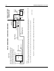
Table Of Contents
- Foreword
- Installation Requirements for Compliance with Radio Frequency (RF) Energy Exposure Safety Standards
- Table of Contents
- Mobile Radio Model Numbering Scheme
- Commercial Warranty
- Chapter 1 Introduction
- Chapter 2 Standard Configurations
- 2.1 Planning the Installation
- 2.2 Radio Mounting
- 2.2.1 Dash Mount with Trunnion
- 2.2.2 Remote Mount with Trunnion
- 2.2.2.1 Transceiver
- 2.2.2.2 Control Head and Remote Mount Cabling
- 2.2.3 Locking Kit (Optional)
- 2.3 Power Cable
- 2.4 Ignition Sense Cable
- 2.5 Antenna Installation
- 2.6 Speaker
- 2.7 Microphone Hang-Up Clip
- 2.8 Completing the Installation
- Chapter 3 Options and Accessories Installation
- Chapter 4 Motorcycle Radio Installation
- 4.1 Motorcycle Radio Description
- 4.2 Installation Overview
- 4.3 Installing the Universal Mounting Plate
- 4.4 Installing the Speaker and Control Head
- 4.4.1 Handlebar Installation with Speaker and Control Head Mounted Together
- 4.4.2 Fuel Tank Console Installation with Speaker and Control Head Mounted Together
- 4.4.3 Handlebar Installation with Speaker and Control Head Mounted Separately
- 4.4.4 Fuel Tank Console Installation with Speaker and Control Head Mounted Separately
- 4.5 Installing the Speaker
- 4.6 Installing the Microphone Hang-Up Clip
- 4.7 Installing Cables
- 4.8 Installing the Weather-Resistant Enclosure
- 4.9 Transceiver and Cabling Installation
- 4.10 Installing the Antenna
- 4.11 Installing the Emergency Switch Option
- 4.12 Installing the External Alarm Relay Option
- 4.13 Installing the Headset Accessory
- 4.14 Horn/Lights Wiring
- 4.15 Emergency Switch Wiring
- Chapter 5 Finishing the Installation: Cable Connection
- Appendix A Replacement Parts Ordering
- Glossary
- Index

6881098C38-O September 17, 2004
Standard Configurations: Radio Mounting 2-13
2. Attach the trunnion bracket using all four 10-16" x 5/8" self-tapping screws provided.
3. Temporarily install the control head (adjusting for proper viewing angle) and fasten it to the
trunnion with two wing screws. Test the installation to be sure the unit does not wobble or feel
“spongy” when you press the buttons.
NOTE: Use all four mounting screws and be sure they are tightly screwed into metal — either a
dashboard support bracket or a backing plate.
Figure 2-21. W4, W5, and W7 Control Head Installation Exploded View
CAUTION: Care must be taken to shield the control head (front
and back) from direct exposure to pressurized water. The
pressurized water from a hose, in most cases, is more severe than
the stated test and conditions in typical environments.
!
C a u t i o n
IMPORTANT
USE A METAL BACKING PLATE
(NOT SUPPLIED) IF MOUNTING
TRUNNION ON A PLASTIC DASHBOARD
DRILL FOUR 5/32"
HOLES IN DASHBOARD
DASHBOARD
TRUNNION
03-00136756
USE FOUR MOUNTING SCREWS
ON ALL INSTALLATIONS
ADJUST THE CONTROL HEAD
TO DESIRED ANGLE AND
SECURE WITH WING SCREWS
VIP CONNECTOR
TO
MICROPHONE
TO
SPEAKER
TO
RADIO
ORANGE AND
GREEN LEADS
MAEPF-21453-O