
Installation Manual


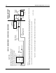
Table Of Contents
- Foreword
- Installation Requirements for Compliance with Radio Frequency (RF) Energy Exposure Safety Standards
- Table of Contents
- Mobile Radio Model Numbering Scheme
- Commercial Warranty
- Chapter 1 Introduction
- Chapter 2 Standard Configurations
- 2.1 Planning the Installation
- 2.2 Radio Mounting
- 2.2.1 Dash Mount with Trunnion
- 2.2.2 Remote Mount with Trunnion
- 2.2.2.1 Transceiver
- 2.2.2.2 Control Head and Remote Mount Cabling
- 2.2.3 Locking Kit (Optional)
- 2.3 Power Cable
- 2.4 Ignition Sense Cable
- 2.5 Antenna Installation
- 2.6 Speaker
- 2.7 Microphone Hang-Up Clip
- 2.8 Completing the Installation
- Chapter 3 Options and Accessories Installation
- Chapter 4 Motorcycle Radio Installation
- 4.1 Motorcycle Radio Description
- 4.2 Installation Overview
- 4.3 Installing the Universal Mounting Plate
- 4.4 Installing the Speaker and Control Head
- 4.4.1 Handlebar Installation with Speaker and Control Head Mounted Together
- 4.4.2 Fuel Tank Console Installation with Speaker and Control Head Mounted Together
- 4.4.3 Handlebar Installation with Speaker and Control Head Mounted Separately
- 4.4.4 Fuel Tank Console Installation with Speaker and Control Head Mounted Separately
- 4.5 Installing the Speaker
- 4.6 Installing the Microphone Hang-Up Clip
- 4.7 Installing Cables
- 4.8 Installing the Weather-Resistant Enclosure
- 4.9 Transceiver and Cabling Installation
- 4.10 Installing the Antenna
- 4.11 Installing the Emergency Switch Option
- 4.12 Installing the External Alarm Relay Option
- 4.13 Installing the Headset Accessory
- 4.14 Horn/Lights Wiring
- 4.15 Emergency Switch Wiring
- Chapter 5 Finishing the Installation: Cable Connection
- Appendix A Replacement Parts Ordering
- Glossary
- Index

September 17, 2004 6881098C38-O
2-12 Standard Configurations: Radio Mounting
2.2.2.2 Control Head and Remote Mount Cabling
For radios equipped with optional remote mount control heads, see
Figure 2-8 or Figure 2-9. For
radios equipped with remote handheld control heads, see Figure 2-11 or Figure 2-12. Choose a
mounting location for the radio, considering accessibility, and control and antenna cable lengths.
2.2.2.2.1 Remote W4, W5, W7, and W9 Model Control Head Installation
Figure 2-20 shows each of the control head models.
If you are required to insert any of the replaceable buttons available with these radios, refer to the
XTL 5000 Basic Service Manual (Motorola publication part number 6881096C73) for further
information.
Figure 2-20. W4, W5, W7, and W9 Control Heads
The recommended mounting surfaces for the control unit are under the dashboard, on the
transmission hump, or on the center console.
Figure 2-21 shows how the trunnion, control head, and
cables should be installed for the W4, W5, and W7 control heads. Figure 2-22 shows the installation
for the W9 model control head.
NOTE: For control head models W4, W5, and W7 only: To seal the control head and meet
U. S. MIL-STD-810D environmental specifications, covers are supplied for protection of the
control head’s rear connector pins. These covers are in the bag that is fastened to the remote
control head’s mounting trunnion.
If the VIP connector is not being used to connect options, the VIP protective cover should be
installed as shown in
Figure 2-23. If the microphone is connected to the front of the control
head, the MIC protective cover should be installed as shown in
Figure 2-23. Alternately, the
microphone can be connected to the rear connector in place of the cover, and the control head
will still be environmentally sealed.
An adjustable trunnion, which allows a number of mounting positions, is supplied for mounting the
control unit. The installation must not interfere with the operation of the vehicle or its accessories, nor
disturb passenger seating or leg room. The control head must be within convenient reach and
viewing of the user.
If the trunnion is mounted on a plastic dashboard, all four mounting screws should penetrate the
dashboard’s supporting metal frame. If that is not possible, use a metal backing plate (not supplied)
to strengthen the installation. Install the control unit as follows:
1. Use the control unit trunnion as a template to mark the mounting holes; drill 5/32" holes. If
mounting on a plastic surface, use a metal backing plate.
W4
W7
W9
W7
W9
W5
W5