
User's Manual

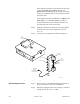


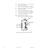
Table Of Contents
- Front Cover
- Contents
- List of Tables
- List of Figures
- Foreword
- Safety and General Information
- Introduction
- System Applications
- Models and Specifications
- Approved Accessories
- Setup and Connections
- Operation
- Troubleshooting
- Introduction
- Recommended Test Equipment
- Troubleshooting Procedures
- Module Replacement Procedures
- Preselector Field Tuning Procedure
- Functional Theory of Operation
- Schematics
- Back Cover

9-42 December 1, 2000 68P81093C75-O
Step 3. Insert the tuning probe into the cavity “U2” and adjust
tuning screw 2 for a PEAK.
Step 4. Tighten tension nut on tuning screw 2 to at least
12 in. – lb. and fine tune tuning screw 2 for a PEAK.
Step 5. Keep the tuning probe in cavity “U2” and adjust
tuning screw 3 for a DIP.
Step 6. Tighten tension nut on tuning screw 3 to at least
12 in. – lb. and fine tune tuning screw 3 for a DIP.
Step 7. Insert the tuning probe into cavity “U3” and decrease
the output from the signal generator to -5 dBm.
Step 8. Adjust tuning screw 4 for a DIP.
Step 9. Tighten tension nut on tuning screw 4 to at least
12 in. – lb. and fine tune tuning screw 4 for a DIP.
Figure 15 Location of Tuning Screws and Cavity Probe Holes
To
Receiver
Board
To
Station Receive
Antenna Port
Preselector
Assembly
MAEPF-27041-O
U2
TUNING SCREW 2
U3
TUNING SCREW 3
U4
TUNING SCREW 4