
User's Manual

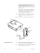


Table Of Contents
- Front Cover
- Contents
- List of Tables
- List of Figures
- Foreword
- Safety and General Information
- Introduction
- System Applications
- Models and Specifications
- Approved Accessories
- Setup and Connections
- Operation
- Troubleshooting
- Introduction
- Recommended Test Equipment
- Troubleshooting Procedures
- Module Replacement Procedures
- Preselector Field Tuning Procedure
- Functional Theory of Operation
- Schematics
- Back Cover
9-40 December 1, 2000 68P81093C75-O
If the frequency (from Step 1) is > 431 MHz, then the
alignment frequency = 431 MHz.
If the frequency (from Step 1) is < 405 MHz, then the
alignment frequency = 405 MHz.
Otherwise, use the actual frequency from Step 1.
Step 3. If Receiver Module is Range 2, determine the
alignment frequency as follows:
If the frequency (from Step 1) is > 468 MHz, then the
alignment frequency = 468 MHz.
If the frequency (from Step 1) is < 440 MHz, then the
alignment frequency = 440 MHz.
Otherwise, use the actual frequency from Step 1.
Step 4. If the Receiver Module is Range 3 or 4, determine the
alignment frequency as follows:
If the frequency (from Step 1) is > 518 MHz, then the
alignment frequency = 518 MHz.
If the frequency (from Step 1) is < 472 MHz, then the
alignment frequency = 472 MHz.
Otherwise, use the actual frequency from Step 1.
For stations with multiple receive frequencies, calculate the
frequencies of the alignment signal as follows:
Step 1. From the site documentation, or the RSS, note the
receive frequency for each channel supported by the
station.
Step 2. Calculate a midpoint frequency as follows:
F
mid
= (F
highest
+ F
lowest
) ÷ 2
Step 3. Using F
mid
in place of the station receive frequency,
perform Step 1 through Step 4 above.
Preparing Equipment Step 1. Make sure the Receiver Module (with the Preselector
Assembly) is installed in a functional PDR 3500.